4 defining the control room, Defining the control room, Figure 9: loading the drivers – Kramer Electronics WP-501 User Manual
Page 18: On 4, Figure 9
Defining the Control Room
11
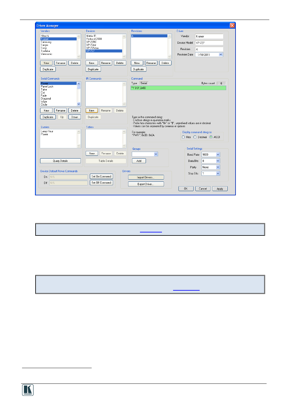
Figure 9: Loading the Drivers
6. Click OK (or Apply and then OK).
The drivers are now installed
The Driver Manager features are defined in
.
4
Defining the Control Room
Section 9
You can define the control devices setup in the room via the Control Room. Depending on the
Master RC, up to four Aux K-NET devices and two Virtual Devices can be used in the same control
setup. At any point you can right click a control device to perform further functions.
It is recommended to open a new project before defining the control room.
At any point, you can save (or save as…) the project, see
Section 1.5
In the following example the SV-552 is selected as the Master room controller, the RC-63DL is the
connected auxiliary panel
and the RC-4 is the IR remote control transmitter.
1
The driver commands appear in the Web Access page
2
Some of the devices in the Add Device list (for example, the WP-500) do not accept auxiliary devices