Figure 29: writing a port description, Figure 30: serial settings window, Figure 31: the port commands – Kramer Electronics WP-501 User Manual
Page 28
Tab Area Settings
21
Figure 29: Writing a Port Description
9. In the same way add a driver to each of the other ports.
10. Click the Properties field to define the Serial settings for the serial ports:
Figure 30: Serial Settings Window
11. When defining the ports of a Master RC which is Site-CTRL compatible, check the radio button
“Main” to select the port which will appear in the main display of the Master RC Web pages
12. If required, change the data field manually (although it changes automatically when setting the
driver), by clicking the relevant properties field:
.
The same display device will be monitored in the Site-CTRL overview page.
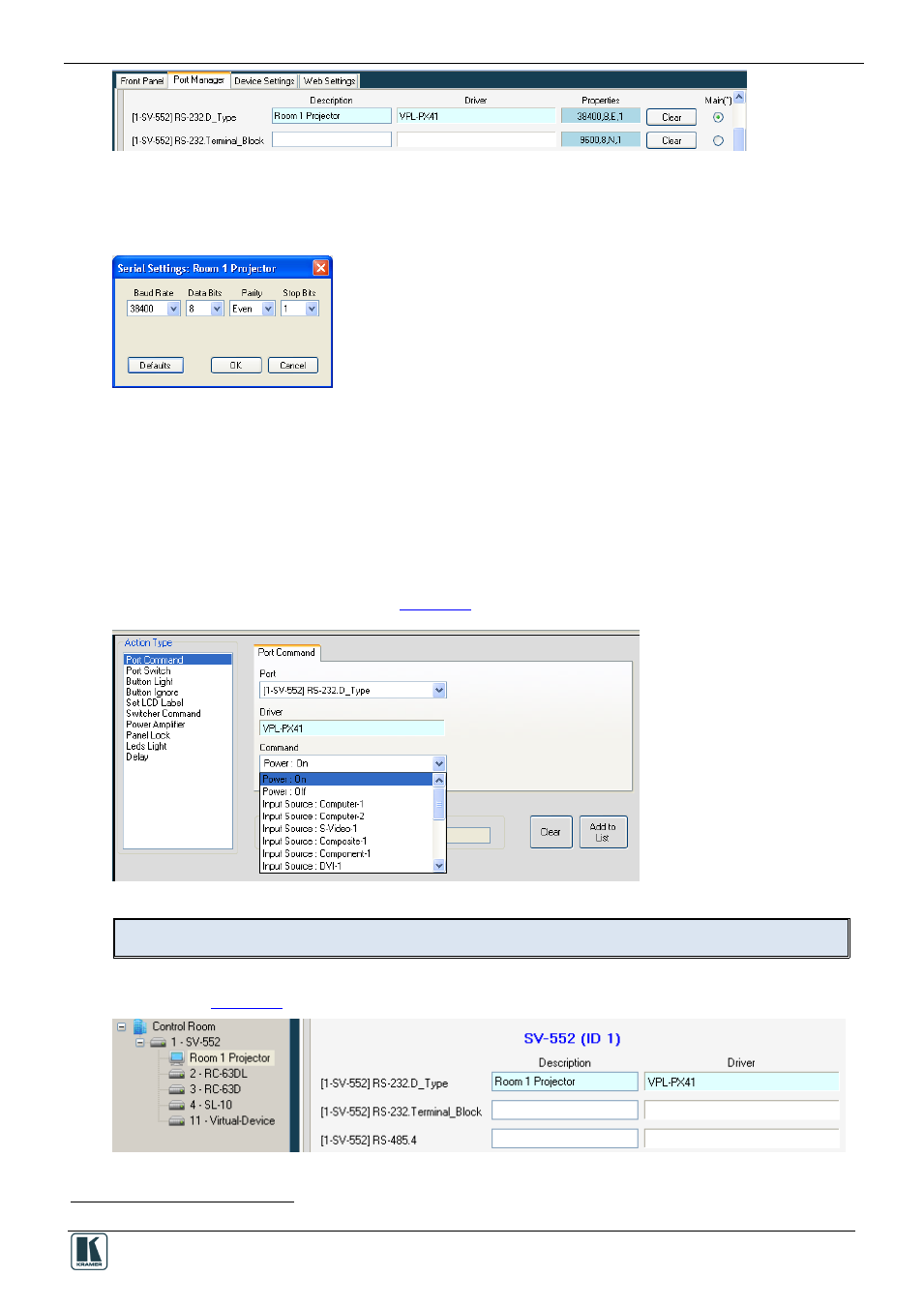
The assigned driver automatically appears in the Port Command tab when the relevant port is
selected. In the example above, RS-232.D_Type port is selected and the command drop-down list
includes all the driver commands (see
Figure 31: The Port Commands
You can, at any time, change the driver either via the Port Manager tab or the Port Driver area.
The assigned driver also appears in the Control Room area under the device it is connected to, as
Figure 32: The Assigned Driver in the Control Room Area
1
The same display device will be monitored in the Site-CTRL overview page