2 digital output, 3 analog input, Digital output – Kramer Electronics WP-501 User Manual
Page 53: Analog input, Figure 92: the gpi/o defined as digital output, Figure 93: the gpi/o trigger properties window
KRAMER: SIMPLE CREATIVE TECHNOLOGY
The Triggers
46
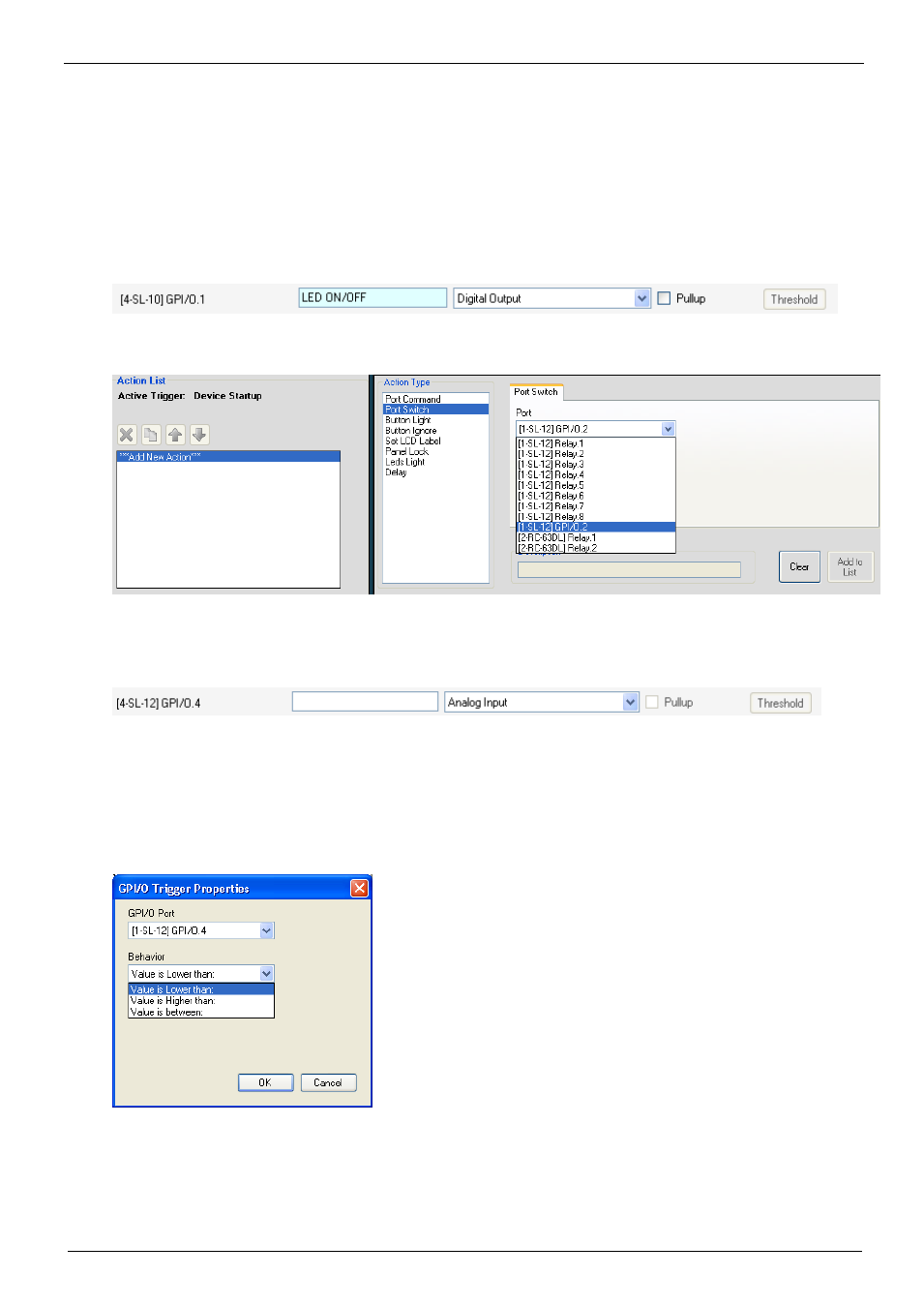
6.8.2 Digital Output
The digital output function is defined by the pull-up setup:
•
Without Pullup: The port will act as a solid state relay (open/close functions)
The GPI/O maximum voltage is 30V DC and the maximum current is 50mA
•
With Pullup: the port can be used as a TTL positive logic output (open: ~2.4V;
closed:~0.2V)
Setting the Digital Output
Define the GPI/O in the port manager:
Once defined as Digital Output, the GPI/O port will appear in Port Switch ->port list, and can be
used like any other relay:
Figure 92: The GPI/O Defined as Digital Output
6.8.3 Analog Input
The analog input accepts an analog signal from an auxiliary device:
The pullup and threshold features are disabled.
The trigger is activated once when the voltage is within a certain range of voltages.
To add a GPI/O Trigger:
1. Click the Add GPI/O Trigger button.
The following window appears:
Figure 93: The GPI/O Trigger Properties Window
2. Select the trigger behavior: