2 the device settings tab, The device settings tab, Figure 40: the device settings tab – Kramer Electronics WP-501 User Manual
Page 31: Figure 41: device selection dialog box, Table 6: connect dialog box, On 5.2, Figure 42, A nd, Table 7
KRAMER: SIMPLE CREATIVE TECHNOLOGY
Tab Area Settings
24
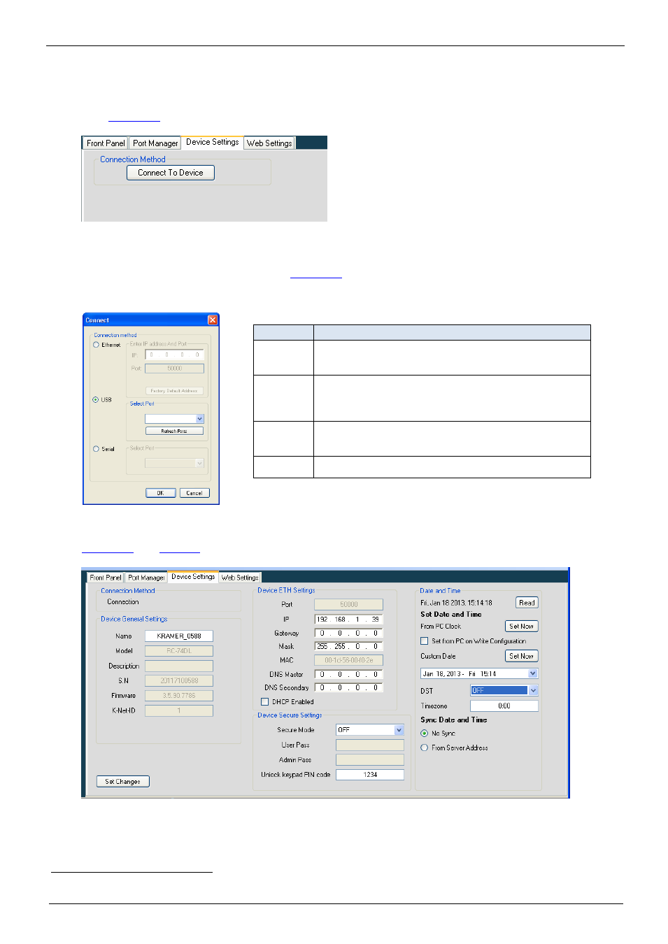
5.2 The Device Settings Tab
Device setting readout is possible with standalone room controllers and K-NET Master RC or Aux
K-NET devices connected with a K-NET cable to their Master RC, as defined in the Room Control
shows the device settings tab:
Figure 40: The Device Settings Tab
1. Click Connect To Device:
The Connect window appears (see
2. Select the connection method to the standalone controller or Master RC.
Figure 41: Device Selection Dialog Box
Table 6: Connect Dialog Box
Feature
Function
Connection
Method Area
Check to select the connection to the device via the Ethernet, USB or
Serial port
Ethernet Area IP: Type the IP address of the device to which you want to connect.
Port: shows the port number.
Factory Default Address Button: Click to reset the IP address to its
default value
USB Area
Port: select the communication USB port.
Refresh Ports: click to check if there are ports ready to connect on the
Kramer device
Serial
Select Port: select the communication port
and
define the device settings after connecting to the device
26F
1
:
Figure 42: The Device Settings Tab (Device with Time Server Options Connected)
1
The actual visible settings change according to the device