Figure 89: gpi/o trigger timeout (digital input), Figure 91: adding actions to the gpi/o trigger, Select the condition for activating the trigger – Kramer Electronics WP-501 User Manual
Page 52: Add actions to the new trigger (s ee figure 91 )
The Triggers
45
4. Select the condition for activating the trigger:
Level moved from High to Low Closing the circuit
or the voltage exceeding its maximum defined value
Level Moved from Low to High
activates the
trigger immediately
Opening the circuit
or the voltage decreasing below its minimum defined value
activates
the trigger immediately
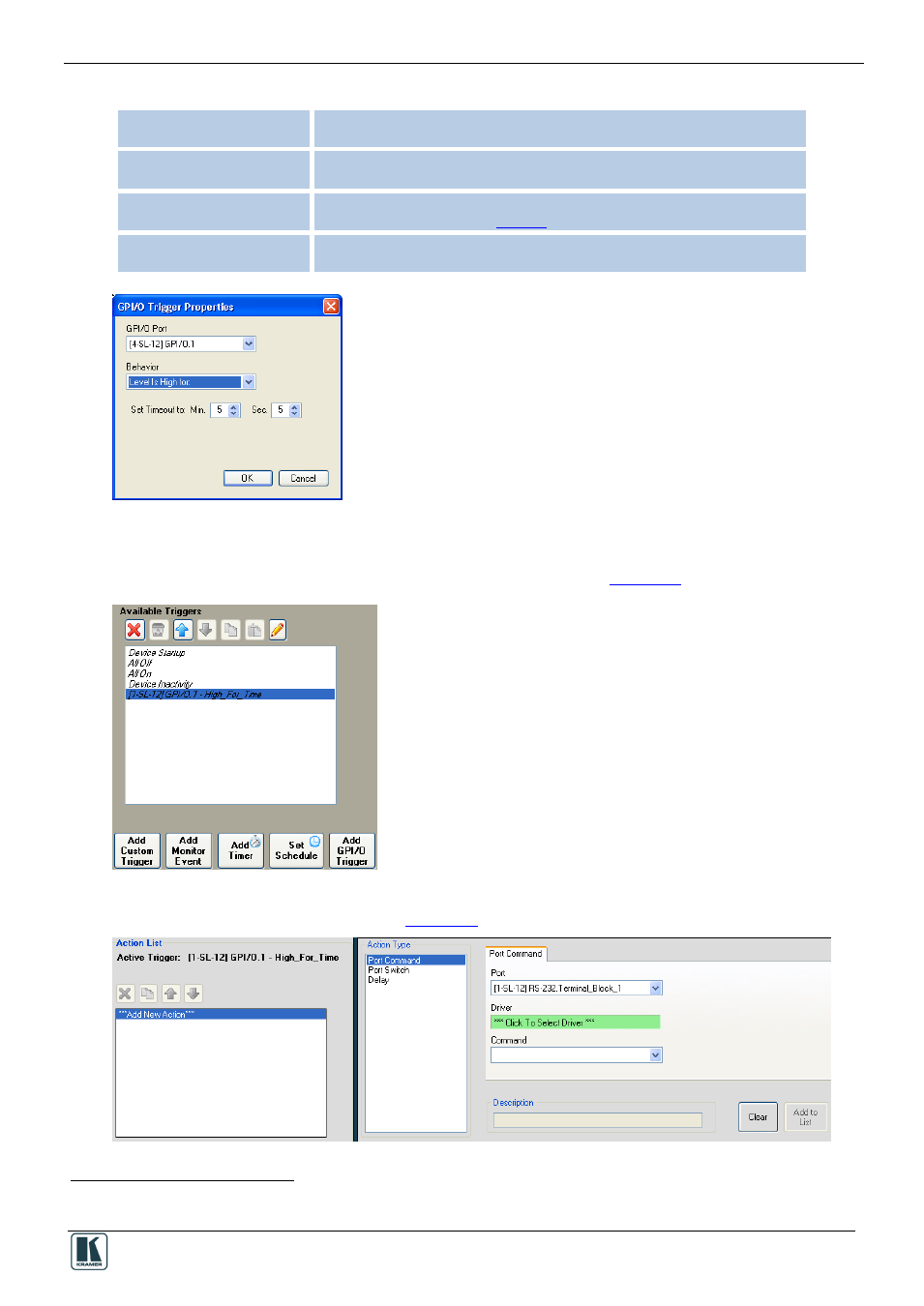
Level is High for:
Circuit remains open
or the voltage exceeding its maximum defined value
and staying
there for a set period of time (see
); the trigger is activated on the first occurrence
Level is Low for:
Circuit remains closed
or the voltage decreasing below its minimum defined value
and
staying there for a set period of time; the trigger is activated on the first occurrence
Figure 89: GPI/O Trigger Timeout (Digital Input)
5. Set the Timeout and click OK.
6. Select the GPI/O trigger from the list of available triggers (see
Figure 90: Selecting the GPI/O Trigger from the Available Triggers List
7. Add actions to the new trigger (see
).
Figure 91: Adding Actions to the GPI/O Trigger
1
Pullup checked
2
Pullup not checked