1 special auxiliary devices, Special auxiliary devices, Figure 15: device operations – Kramer Electronics WP-501 User Manual
Page 21
KRAMER: SIMPLE CREATIVE TECHNOLOGY
Defining the Control Room
14
Note: Be sure that your control room setup tree is correct before continuing with the
configuration. If, at a later stage, an auxiliary K-NET device or a Master RC will be deleted from
the tree, all the port assignments, triggers and action lists written for all the devices in the tree
will also be deleted
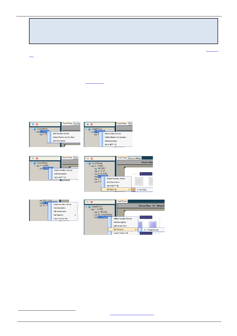
You can right-click a device to carry out several operations, as illustrated in the examples in
•
Add a device (Master RC only)
•
Delete a device
•
Add a description that will appear in the Device View area
•
Set the K-NET™ ID (see
Section 8
•
Edit the device view (virtual device only)
•
If the setup includes two or more identical AUX panels – you can set some of them to be
the “exact same as” another AUX/Master device (so they will behave in the exact same
manner)
•
Export a device (for virtual devices only)
Virtual Device
Virtual Device
Master Room Controller
Master Room Controller
Auxiliary Device
Auxiliary Device
Figure 15: Device Operations
4.1 Special Auxiliary Devices
This section describes some of the auxiliary devices in more detail.
4.1.1 The Virtual Device – Compatible with SL-1, SL-10, SL-12, SL-14RC, RC-74DL, SV-551
and SV-552
A virtual auxiliary application can be developed
1 See the Kramer "Virtual Device Build Guidelines" on our Web site a
by the installer and used as a virtual user room
control interface under a common OS (iOS
®
, Android™ and so on) to control room functions via IT
infrastructures. To support the Virtual Device application, a Virtual Device triggers layer must be
defined by K-Config. This layer will associate triggers sent from the virtual application to the