Input scaling, Scaling – West Control Solutions Pro-16 User Manual
Page 57
Input
scaling
9499-040-93811 / 59537-1
Page 57 of 88
Pro-16
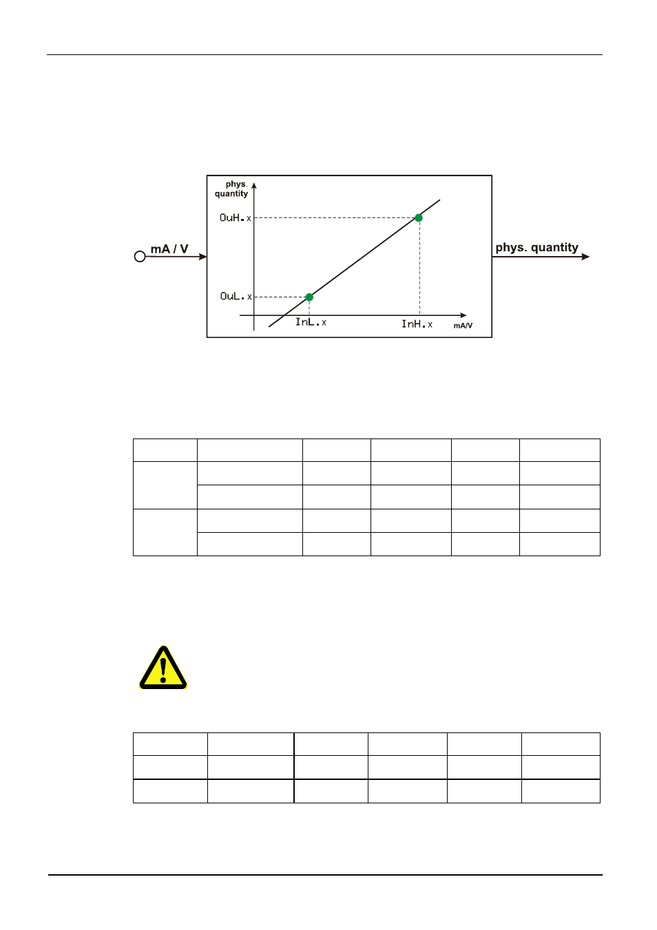
6. Input scaling
When using current or voltage signals as input variables for
InP.1 or InP.2,
scaling of input and display values at parameter setting level is required. Specification of
the input value for lower and higher scaling point is in the relevant electrical unit (mA/ V).
Input
Inp.1
g
Parameter
InL.1 , OuL.1, InH.1 und OuH.1 are only visible if
ConF / InP.1 / Corr = 3 is chosen.
S.tYP Input
signal
InL.1 OuL.1 InH.1 OuH.1
30
(0...20mA)
0 … 20 mA DC
0 -1999...9999 20 -1999...9999
4 … 20 mA DC
4 -1999...9999 20 -1999...9999
40
(0...10V)
0 … 10 V
0 -1999...9999 10 -1999...9999
2 … 10 V
2 -1999...9999 10 -1999...9999
In addition to these settings,
InL.1 and InH.1 can be adjusted in the range
(0...20mA / 0...10V) determined by selection of
S.tYP .
For using the predetermined scaling with thermocouple and resistance
thermometer (Pt100), the settings of
InL.1 and OuL.1 as well as of
InH.1 and OuH.1 must correspond.
Input
InP.2
S.tYP
Input signal
InL.2 OuL2 InH.2 OuH.2
30
0 … 20 mA DC
0 -1999...9999 20 -1999...9999
31
0 … 50 mA AC
0 -1999...9999 50 -1999...9999
In addition to these settings,
InL.2 and InH.2 can be adjusted in the range
(0...20/ 50mA) determined by selection of
S.tYP.