5 errorlist / maintenance manager – West Control Solutions Pro-16 User Manual
Page 12
Operation
9499-040-93811 / 59537-1
Page 12 of 88
Pro-16
3.5 Errorlist / Maintenance Manager
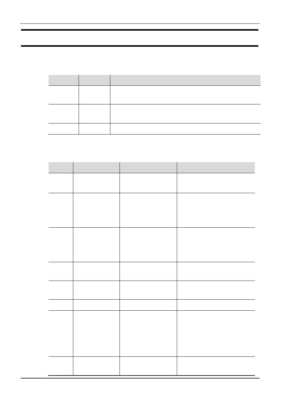
The error list is visible only if an error entry is present. An active entry in the error list is
displayed by a red/green blinking 2nd line and status LED’s in the display.
Err-Status Signification Proceed as follows
2. line
blinks red
existing
error
- determine the error type in the error list via the error number
- remove error
.. is red
error
removed
- Acknowledge the alarm in the error list by pressing key
È
- or
È
- The alarm entry is deleted.
.. is green
no error
All errors can be reset in the function level with
Err
È
rSET (if configured).
3.5.1
Error-List:
Name
Description
Cause
Possible remedial action
E.1 Internal error,
cannot be removed
E.g. defective EEPROM
Contact PMA service
Send- in device
E.2 Internal error, can
be reset
e.g. EMC trouble
-shortly separate the device from
mains supply
- Keep measurement and power
supply cables in separate runs
E.4
Internal error,
option modules
HW-Coding does not
match the current
recognized HW
configuration
- Contact PMA service, send-in
device or check option modules
FBF.
1/2
Sensor break
INP1/2
Sensor defectiveFaulty
cabling
Replace INP1/2 sensor
Check INP1/2 connection
Sht.
1/2
Short circuit
INP1/2
Sensor defectiveFaulty
cabling
Replace INP1/2 sensor
Check INP1/2 connection
POL.1 INP1 polarity error Faulty cabling
Reverse INP1 polarity
HCA
Heating current
alarm
- Heating current circuit
interrupted, I <
HC.A
or I >
HC.A (dependent
of configuration)
- Heater band defective
-Check heating
current circuit
- If necessary, replace
heater band
SSR
Heating current
short circuit
- Current flow in
heating
- Check heating current circuit
- If necessary, replace solid-