Operation – KROHNE OPTISONIC 7300 EN User Manual
Page 75
OPERATION
6
75
OPTISONIC 7300
www.krohne.com
09/2012 - 4001102303 - MA OPTISONIC 7300 R03 en
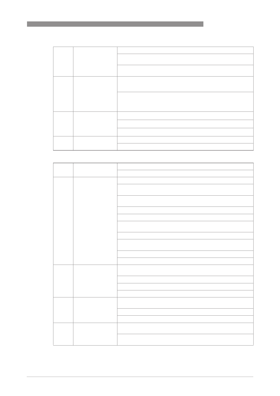
C2. .9
invert signal
Select:
Off
(activated output generates a high current at the output, switch closed)
On
(activated output generates a low current at the output, switch open)
C2. .10 phase shift w.r.t. B
Only available when configuring the A or D terminal and only if output
B is a pulse or frequency output. If setting in Fct. 2.5.6 is "both
polarities", the phase shift is prefixed by a symbol, e.g. -90° and +90°.
Select: off (no phase shift) /
0° phase shift (between outputs A or D and B, inversion possible) /
90° phase shift (between outputs A or D and B, inversion possible) /
180° phase shift (between outputs A or D and B, inversion possible)
C2. .11 information
1
st
line: serial number of the I/O circuit board
2
nd
line: software version number
3
rd
line: production date of the circuit board
C2. .12 simulation
Simulation of pulse output.
Sequence see B1. pulse output X
status output X
C2.
status output X
X (Y) stands for one of the connection terminals A, B, C or D.
stands for A, B, C or D.
C2. .1
mode
The output shows the following measuring conditions:
Out of specification (output activated, signals application error or error
in device. Please refer to
Error messages
on page 85).
Application error (output activated, signals application error or error in
device. Please refer to
Error messages
on page 85).
Polarity flow (polarity of the current flow)
Over range flow (over range of the flow)
Counter 1 or 2 preset (activates counter X when preset value is
reached)
Counter 3 preset (only available for special I/O)
Output A, B, C or D (activated by the status of output Y, additional
output data see below)
Off (switched off)
Error in device (when error, output activated)
C2. .2
current output Y
Only appears if output A...C is set under "mode" (see above), and this
output is a "current output".
Polarity (is signaled)
Over range (is signaled)
Range change C
C2. .2
frequency output Y
and pulse output Y
Only appears if output A, B or D is set under "mode" (see above), and
this output is a "frequency/pulse output".
Polarity (is signaled)
Over range (is signaled)
C2. .2
status output Y
Only appears if output A...D is set under "mode" (see above), and this
output is a "status output".
Same signal (like other connected status output, signal can be
inverted, see below)