Wiring, 1 general, Caution – Yokogawa Integral Oxygen Analyzer ZR202 User Manual
Page 57
IM 11M13A01-04E
5-1
5. Wiring
5.
Wiring
This chapter describes wiring procedures necessary for the EXAxtZR Integrated-type
Explosionproof Zirconia Oxygen Analyzer.
5.1
General
CAUTION
Be sure to read Sections 3.1.2 to 3.1.4 where the important information on wiring is
provided.
CAUTION
• Never supply current to the equipment or any other device constituting a power circuit
in combination with the equipment, until all wiring is completed.
• This product complies with CE marking.
Where a performance suit for CE marking is necessary, the following wiring proce-
dure is necessary.
1. Install an external switch or circuit breaker to the power supply of the equipment.
2. Use an external switch or circuit breaker rated 5A and conforms to IEC 947-1 or IEC
947-3.
3. It is recommended that the external switch or circuit breaker be mounted in the same
room as the equipment.
4. The external switch or circuit breaker should be installed within the reach of the
operator, and marked as the power supply switch of this equipment.
Wiring procedure
Wiring should be made according to the following procedure:
1. Be sure to connect the shield of the shielded line to FG terminal of the analyzer.
2. The most outer sheath of the signal line and the power cable should be stripped off
to the minimum necessary length.
3. Signal will be affected by noise emission when the signal lines, power cable are
located in the same conduit. When using a conduit, signal lines should be installed in
the separate conduit from power cables. Be sure to ground the metal conduit.
4. Mount the attached two blind plugs to unused cable connection gland(s) of the
equipment.
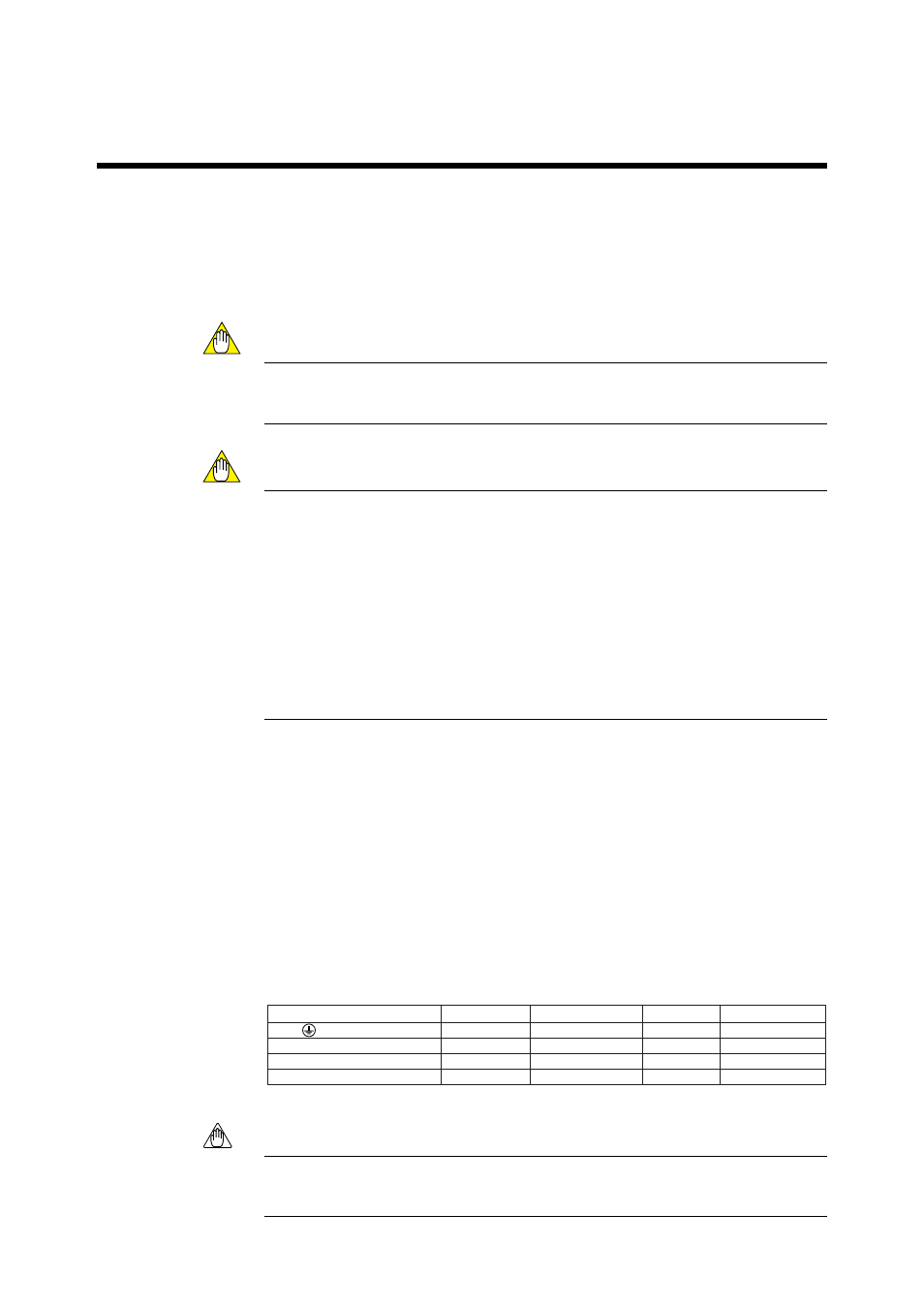
5. The cables indicated in Table 5.1 are used for wiring.
6. After completing the wiring, screw the cover in the terminal box body and secure it
with a lock screw.
Table 5.1 Cable Specifications
Terminal name of equipment
Name
Needs for shields Cable type
Number or wires
L, N,
Power supply
CVV
2 or 3 *
AO+, AO-
Analog output
᭺
CVVS
2
DO-1, DO-2
Contact output
CVV
2 to 8
DI-1, DI-2, DI-C
Contact input
CVV
3
Note *: When the case is used for protective grounding, use a 2-wire cable.
T5.1E.EPS
Note
• Select an appropriate cable O.D. for the cable gland size.
• Protective grounding should have the grounding resistance of 100
⍀ or less.