2 piping for the calibration gas, 3 piping for the reference gas inlet, 4 piping for the reference gas outlet – Yokogawa Integral Oxygen Analyzer ZR202 User Manual
Page 53
IM 11M13A01-04E
4-3
4. Piping
4.1.2
Piping for the Calibration Gas
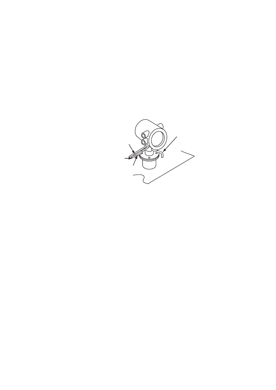
This piping is to be installed between the zero gas cylinder and the ZA8F flow setting
unit, and between the ZA8F flow setting unit and the ZR202S analyzer.
The cylinder should be placed in a calibration gas unit case or the like to avoid any
direct sunlight or radiant heat so that the gas cylinder temperature may not exceed 40˚C.
Mount the pressure regulator (recommended by YOKOGAWA) on the cylinder.
Mount the stop valve or the check valve (recommended by YOKOGAWA) through the
nipple (commercially available) at the calibration gas inlet of the equipment as illus-
trated in Figure 4.8. (The stop valve or the check valve may have been mounted on the
equipment when shipped.) Connect the flow setting unit and the analyzer to a 6mm
(O.D.) x 4mm (I.D.) (or nominal size 1/4 inches) or larger stainless steel pipe.
F4.8E.EPS
Stop valve or check valve
Piping for the reference gas
6mm (O.D.) by 4mm (I.D.)
stainless steel pipe
Piping for the calibration gas
6mm (O.D.) by 4mm (I.D.)
stainless steel pipe
Piping for the reference gas outlet
6mm (O.D.) by 4mm (I.D.)
stainless steel pipe
Figure 4.8 Piping for the Calibration Gas Inlet
4.1.3
Piping for the Reference Gas Inlet
Reference gas piping is required between the air source (instrument air) and the flow
setting unit, and between the flow setting unit and the analyzer.
Insert the air set next to the flow setting unit in the piping between the air source and
the flow setting unit.
Use a 6mm (O.D.) x 4mm (I.D.) (or nominal size 1/4 inch) stainless steel pipe between
the flow setting unit and the analyzer.
4.1.4 Piping for the Reference Gas Outlet
If ZR202S is exposed to rain or water splash, connect the pipe outlet on downward.