1 piping for system 1, 1 piping parts for system 1, Piping in system 1 is illustrated in figure 4.7 – Yokogawa Integral Oxygen Analyzer ZR202 User Manual
Page 52
IM 11M13A01-04E
4-2
4.1
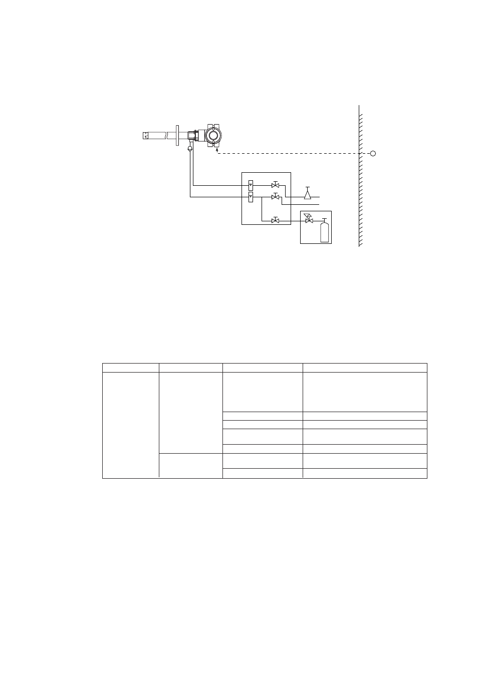
Piping for System 1
Piping in System 1 is illustrated in Figure 4.7.
~
ZR202S Integrated type Explosionproof
Zirconia Oxygen Analyzer
F06.EPS
ZA8F flow setting unit
Reference gas
Calibration gas
Needle
valve
Flowmeter
Instrument air
Air Set
Pressure regulator
Zero gas
cylinder
Stop valve
or
Check valve
Span gas (*4)
Non-hazardous Area
Hazardous Area
100 to 240 V AC
Figure 4.7 Piping for System 1
System 1 illustrated in Figure 4.7 requires piping as follows:
• Mount the check valve or the stop valve through a nipple to the calibration gas inlet of
the equipment.
4.1.1
Piping Parts for System 1
Check that the parts listed in Table 4.1 are provided.
Table 4.1 Piping Parts
Equipment
Piping location
Parts
Description
General-use
Calibration gas inlet Stop valve or check valve
Stop valve (L9852CB or G7016XH
Oxygen Analyzer
recommended by YOKOGAWA
Check valve (K9292DN or K9292DS)
provided by YOKOGAWA
Nipple *
Rc1/4 or 1/4 NPT Commercially available
Zero gas cylinder
User
Јs scope
Regulator valve
(G7013XF or G7014XF) recommended by
YOKOGAWA
Joint for tube connection
Rc1/4 or 1/4 NPT Commercially available
Reference gas inlet
Air set
(K9473XH / K9473XJ or G7004XF
/ K9473XG) recommended by YOKOGAWA
Joint for tube connection
Rc1/4 or 1/4 NPT Commercially available
Note: Parts marked with * are used when required.
T4.2E.EPS