2 measures taken when alarms are generated – Yokogawa Integral Oxygen Analyzer ZR202 User Manual
Page 159
IM 11M13A01-04E
12-5
12. Troubleshooting
12.2.2
Measures Taken When Alarms are Generated
12.2.2.1
Alarm 1: Oxygen Concentration Alarm
This alarm is generated when a measured value exceeds an alarm set point or falls
below it. For details on the oxygen concentration alarm, see Section 8.4, “Setting
Oxygen Concentration Alarms” in the chapter on operation.
12.2.2.2
Alarm 6: Zero-point Calibration Coefficient Alarm
In calibration, this alarm is generated when the zero correction factor is out of the
range of 100
Ϯ 30% (refer to Section 9.1.3, “Compensation”). The following can be
considered the causes for this:
(1) The zero-gas oxygen concentration does not agree with the value of the zero-gas
concentration set “Calibration Setup”. Otherwise, the span gas is used as the zero
gas.
(2) The zero-gas flow is out of the specified flow (600
Ϯ 60 ml/min).
(3) The sensor assembly is damaged and so cell voltage is not normal.
their proper states, correct them.
a. If the indication for “Zero gas conc” is selected in “Calibration setup” the set value
should agree with the concentration of zero gas actually used.
b. The calibration gas tubing should be constructed so that the zero gas does not leak.
(2) If no alarm is generated as a result of carrying out re-calibration, it is suspected that
improper calibration conditions were the cause of the alarm in the preceding calibra-
tion. In this case, no specific restoration is necessary.
(3) If an alarm is generated again as a result of carrying out re-calibration, deterioration
of or damage to the sensor assembly is suspected as the cause of the alarm. Replace-
ment of the cell with a new one is necessary. However, before replacement, carry out
the following:
Check the cell voltages when passing the zero gas and span gas.
a. Display the cell voltage with the parameter code A11.
b. Check whether or not the value of the displayed cell voltage is very different from
the theoretical value at each oxygen concentration. Confirm the theoretical values of
the cell voltage in Table 12.3. Although it cannot be generally specified as to what
extent the difference from the theoretical value is allowed, consider it to be approxi-
mately
Ϯ10 mV.
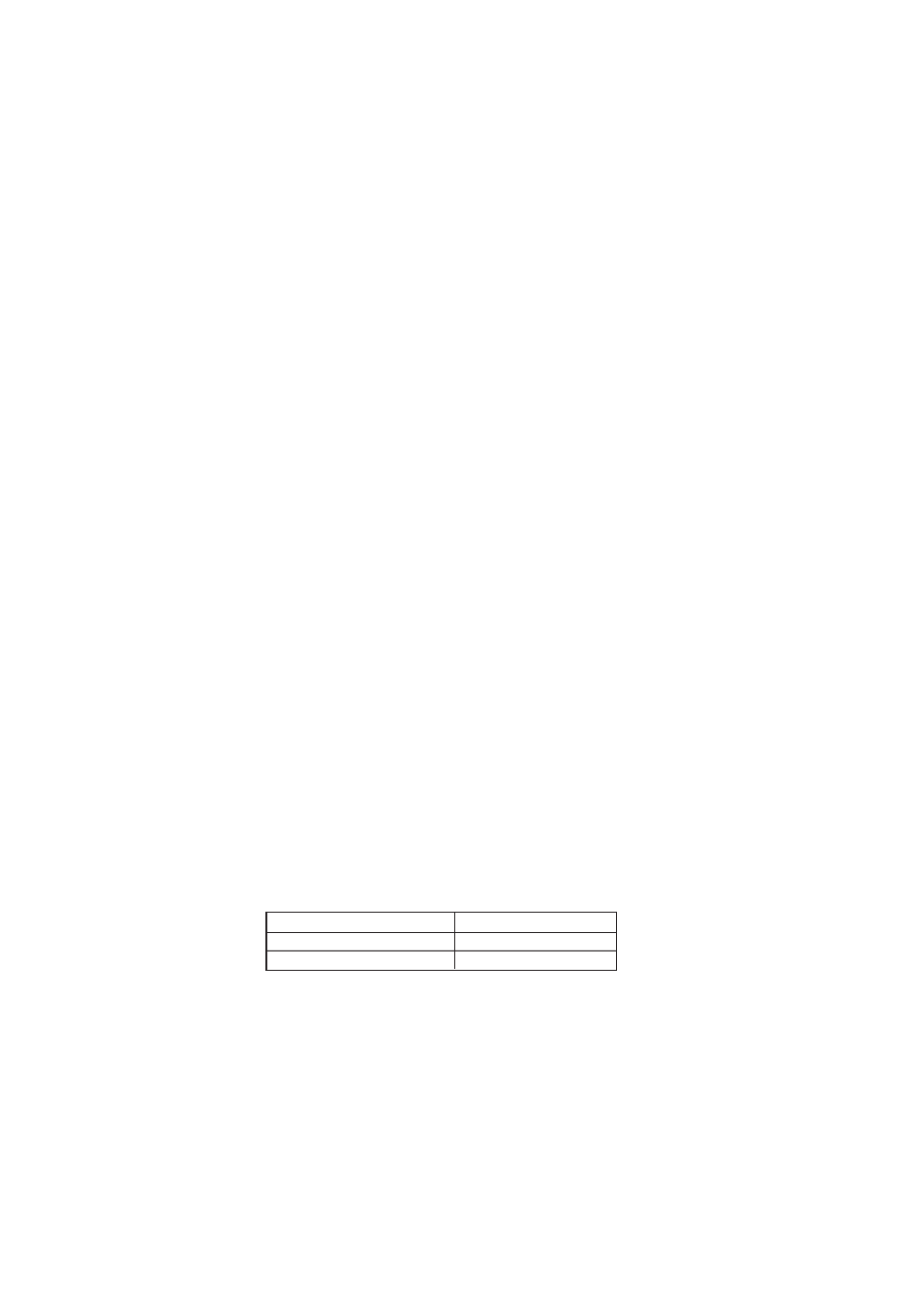
Table 12.3 Oxygen Concentration and Cell Voltage Oxygen concentration
Oxygen concentration (% O
2
) Cell voltage (mV)
1%
67.1
21%
0
T12.3.EPS
(4) Confirm whether deterioration of or damage to the sensor assembly that caused the
alarm has occurred abruptly during the current calibration in the following procedure:
Check the history of the span gas ratio with the parameter codes A50 and A51.
Check the history of the zero gas ratio with the parameter codes A60 through A69.
The larger the parameter code number, the older the displayed data. Changes in
deterioration of the sensor can be seen.