2 system 2, Gas (n, Based) – Yokogawa Integral Oxygen Analyzer ZR202 User Manual
Page 17
IM 11M13A01-04E
1-3
1. Overview
1.1.2
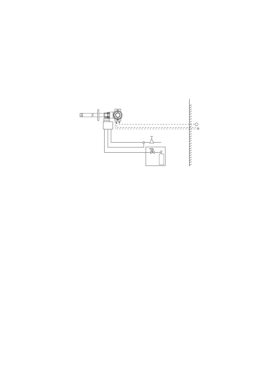
System 2
This example, System 2, represents typical applications in large boilers and heating
furnaces, where is a need to monitor and control oxygen concentration. The reference
gas and calibration-time span gas are (clean, dry) instrument air. Zero gas is supplied
from a gas cylinder.
System 2 uses the autocalibration unit, with auto-switching of the calibration gas. A
“combustible gas detected” contact input turns off power to the heater. There’s also
contact output from the converter that can be used to operate a purge gas valve to supply
air to the sensor.
~
100 to 240 V AC
Auto Calibration unit
Reference gas
Calibration gas (Zero)
Contact input
Analog output, contact output
Digital output (HART)
Air Set
Instrument air
Calibration gas
unit case
Pressure regulator
Zero gas cylinder
ZR202S Integrated type Explosionproof
Zirconia Oxygen Analyzer
F03.EPS
Span gas
ZR20S
*3
Non-hazardous area
Hazardous area
Note:
The installation temperature limits range for integrated type analyzer is -20 to 55
؇
C.
*2
*1 Shield cable:
Use shielded signal cables, and connect the shields to the FG terminal of the
converter.
*2 Select the desired probe from the Probe Configuration table on page 1-4.
*3 When a zirconia oxygen analyzer is used, 100% N
2
gas cannot be used as the zero
gas. Use approx. 1 vol% O
2
gas (N
2
-based).