4 insulation resistance test – Yokogawa Integral Oxygen Analyzer ZR202 User Manual
Page 50
IM 11M13A01-04E
3-10
3.4
Insulation Resistance Test
Even if the testing voltage is not so great that it causes dielectric breakdown, testing
may cause deterioration in insulation and a possible safety hazard. Therefore, conduct
this test only when it is necessary.
The applied voltage for this test shall be 500 V DC or less. The voltage shall be applied
for as short a time as practicable to confirm that insulation resistance is 20 M
⍀ or more.
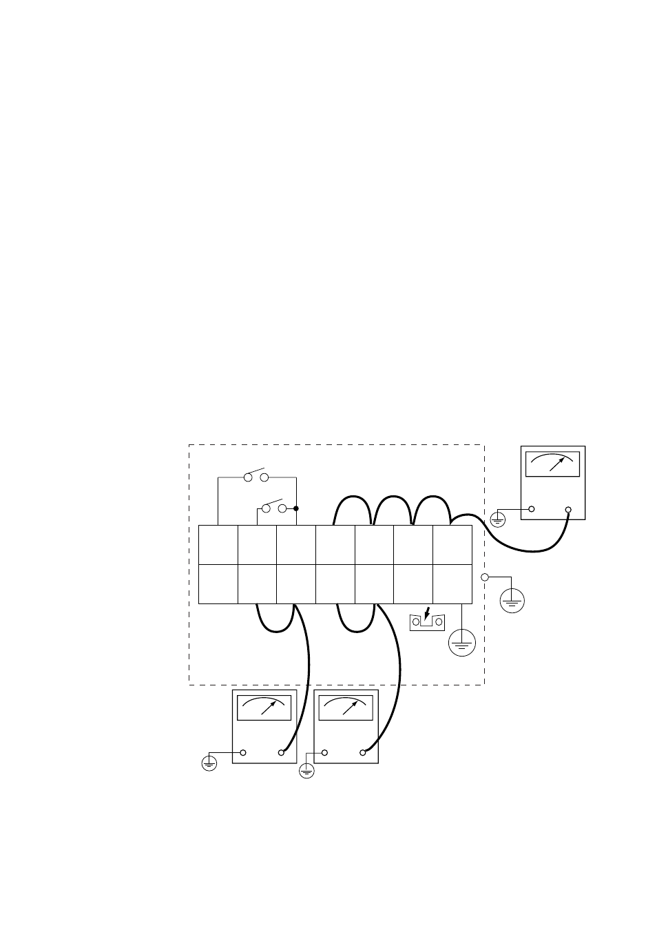
Remove wiring from the converter and detector.
1. Remove the jumper plate located between terminal G and the protective grounding
terminal.
2. Connect crossover wiring between L and N.
3. Connect an insulation resistance tester (with its power OFF). Connect (+) terminal to
the crossover wiring, and (-) terminal to ground.
4. Turn the insulation resistance tester ON and measure the insulation resistance.
5. After testing, remove the tester and connect a 100 k
⍀ resistance between the cross-
over wiring and ground, to discharge.
6. Testing between the heater terminal and ground, contact output terminal and ground,
analog output/input terminal and the ground can be conducted in the same manner.
7. Although contact input terminals are isolated, insulation resistance test cannot be
conducted because the breakdown voltage of the surge-preventing arrester between
the terminal and ground is low.
8. After conducting all the rests, replace the jumper as it was.
1
DI-1
2
DI-2
3
DI-C
4
DO-1
5
DO-1
6
DO-2
7
DO-2
8
FG
9
AO
(+)
10
AO
(-)
11
L
12
N
13
G
14
FG
F3.17E.EPS
Remove
jumper
plate
Insulation
resistance
tester
Insulation
resistance
tester
Crossover wiring
Crossover wiring
Contact input 1
Contact input 2
+
-
+
-
Insulation
resistance
tester
+
-
Figure 3.6 Insulation Resistance Test