Caution, 6 probe insertion hole – Yokogawa Integral Oxygen Analyzer ZR202 User Manual
Page 46
IM 11M13A01-04E
3-6
3.1.6
Probe Insertion Hole
CAUTION
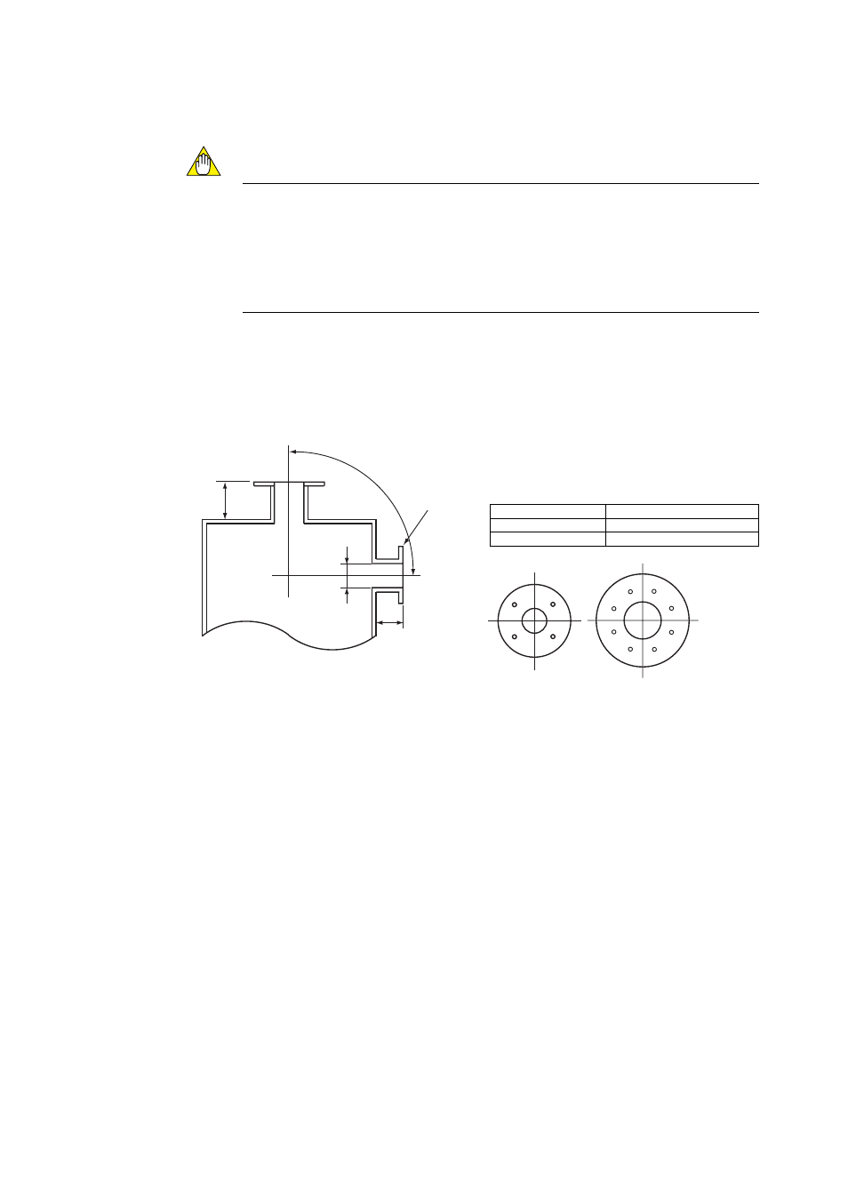
• The outside dimension of detector may vary depending on its options. Use a pipe that
is large enough for the detector. Refer to Figure 3.3 for the dimensions.
If the detector is mounted horizontally, the calibration gas inlet and reference gas
inlet should face downwards.
• The sensor (zirconia cell) at the probe tip may deteriorate due to thermal shock if
water drops are allowed to fall on it, as it is always at high temperature.
(1) Do not mount the probe with the tip higher than the probe base.
(2) The detector probe should be mounted at right angles to the measurement gas flow or
the probe tip should point downstream.
Figure 3.3 illustrates an example of the probe insertion hole.
100 mm
100 mm
F3.1E.EPS
(vertical)
Bounds of the probe
insertion hole area
Flange matches
the detector size
(horizontal)
Type
Outside diameter of detector
Standard
52 mm in diameter (Note)
With probe protector 60.5 mm in diameter (Note)
Four-hole flange Eight-hole flange
*1
*1
Figure 3.3 Example of forming probe insertion hole