Caution, 7 installation of the probe, 8 installation of the probe protector (zo21r) – Yokogawa Integral Oxygen Analyzer ZR202 User Manual
Page 47
IM 11M13A01-04E
3-7
3. Installation
3.1.7
Installation of the Probe
CAUTION
• The cell (sensor) at the tip of the detector is made of ceramic (zirconia). Do not drop
the detector, as impact will damage it.
• A gasket should be used between the flanges to prevent gas leakage. The gasket
material should be heatproof and corrosion-proof, suited to the characteristics of the
measured gas.
The following should be taken into consideration when mounting the general-use
detector:
(2) Where the detector is mounted horizontally, the calibration gas inlet and the refer-
ence gas inlet should face downward.
3.1.8
Installation of the Probe Protector (ZO21R)
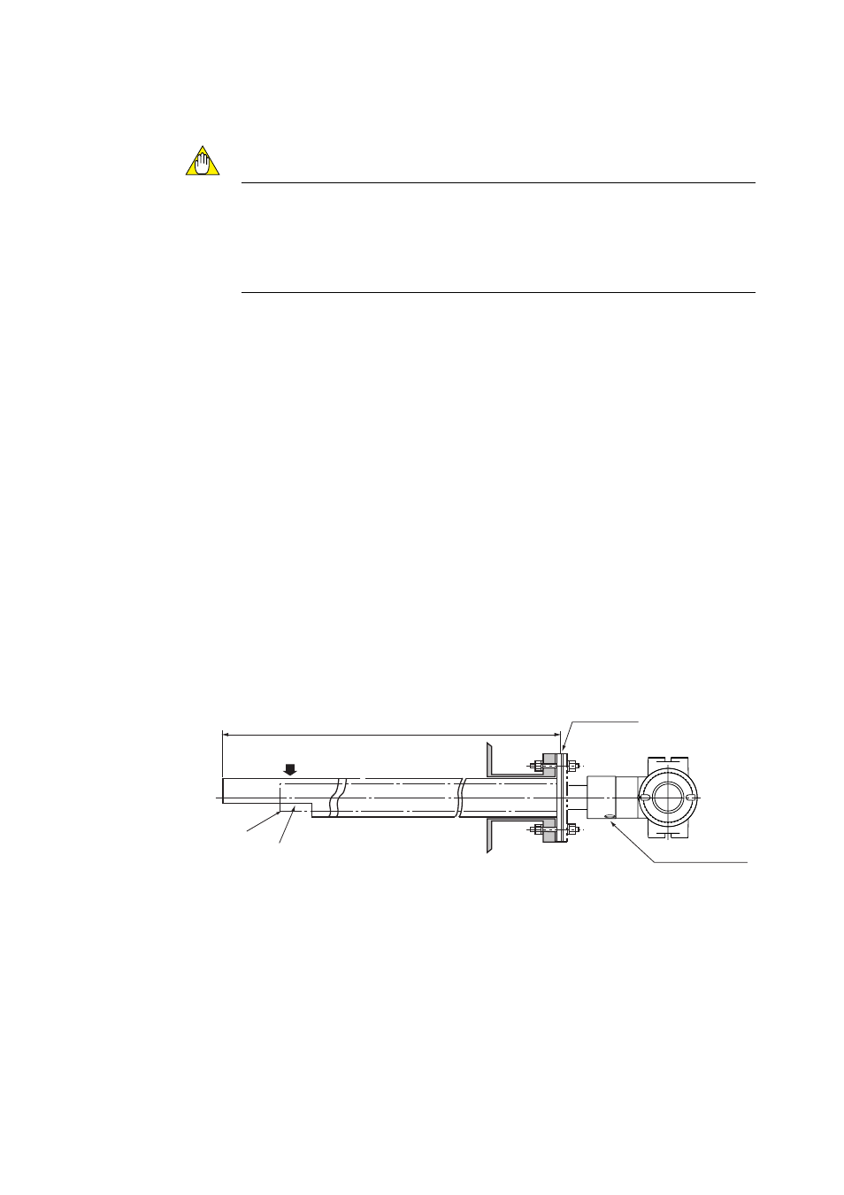
ᮀᮀᮀ-ᮀ *B for dust wear protect> The detector is used with a probe protector to prevent the sensor from being worn by (1) Put the gasket that is provided by user between the flanges, and mount the probe protector in the probe insertion hole. The probe protector should be installed so that (2) Make sure that the cell assembly mounting screws (four) at the probe tip are not loose. (3) Where the detector is mounted horizontally, the calibration/reference gas inlet should face downward. Direction of the measured gas flow Mount the protector so that the notch Unit: mm F3.4E.EPS 1050 Gasket (t1.5) Calibration gas inlet Detector top Figure 3.4 Mounting of detector with a probe protector (Dust wear protect)
dust particles when there is a high concentration of dust and gas flow exceeds 10m/s
(fine-carbon boiler or fluid-bed furnace).
the notch comes to the downstream of the measurement gas flow.
is on the downstream side of gas flow.
Reference gas inlet