Appendix 2. integrator (it) block, A2.1 schematic diagram of integrator block, A2.1 – Yokogawa EJX930A User Manual
Page 85: A2-1
A2-1
IM 01C25T02-01E
Appendix 2. Integrator (IT) Block
The Integrator (IT) block adds two main inputs and integrates them for output. The block compares the
integrated or accumulated value to TOTAL_SP and PRE_TRIP and generates discrete output signals OUT_
TRIP or OUT_PTRIP when the limits are reached.
The output is as represented by the following equation (for counting upward and rate conversion).
OUT.Value = Integration start value + Total
Total = Total + Current Integral
Current Integral = (x + y) × Δt
x: IN_1 value whose unit has been converted
y: IN_2 value whose unit has been converted
Δt: block execution period
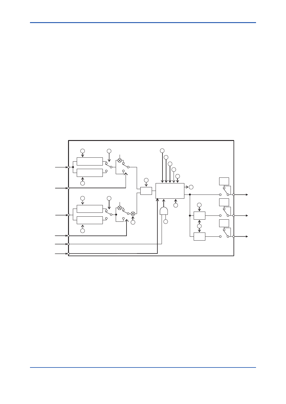
A2.1 Schematic Diagram of Integrator Block
The following shows the schematic diagram of the Integrator block.
OUT
–1
TIME_UNIT2
PULSE_VAL2
–1
UNIT_CONV
OP_CMD_INT
(RESET)
INTEG_OPTS
(CARRY)
Reverse
Forward
Forward
OUT_PTRIP
OUT_TRIP
INTEG_OPTS
(FROW TYPE)
Add
Compare
Compare
TOTAL / RTOTAL
Integrate
INTEG_TYPE
INTEG_OPTS (QUALITY)
GOOD_LIM
UNCERT_LIM
CLOCK_PER
N_RESET
MAN
MAN
MAN
Convert Rate
Convert Accum
Convert Rate
Convert Accum
TOTAL_SP
PRE_TRIP
INTEG_OPTS
(INPUT TYPE)
PULSE_VAL1
TIME_UNIT1
INTEG_OPTS
(INPUT TYPE)
Reverse
FA0201.ai
IN_1
RESET_IN
REV_FLOW1
IN_2
REV_FLOW2
RESET_CONFIRM
IN_1: Block input 1 (value and status)
IN_2: Block input 2 (value and status)
REV_FLOW1: Indicates whether the sign of IN_1 is reversed. It is a discrete signal.
REV_FLOW2: Indicates whether the sign of IN_2 is reversed. It is a discrete signal.
RESET_IN: Resets the integrated values. It is a discrete signal.
RESET_CONFIRM: Reset confirmation input. It is a discrete signal.
OUT: Block output (value and status)
OUT_PTRIP: Set if the target value exceeds PRE_TRIP. It is a discrete signal.
OUT_TRIP: Set if the target value exceeds TOTAL_SP (or 0). It is a discrete signal.
The Integrator block is classified into the following five sections for each function:
• Input process section: Determines the input value status, converts the rate and accumulation, and
determines the input flow direction.
• Adder: Adds the two inputs.
• Integrator: Integrates the result of the adder into the integrated value.
• Output process section: Determines the status and value of each output parameter.
• Reset process section: Resets the integrated values.
Figure A2.1 Integrator Block