Yokogawa EJX930A User Manual
Page 57
<7. In-Process Operation>
7-5
IM 01C25T02-01E
Table 7.4
Relationship between WRITE_LOCK_
LEVEL and block targeted by write lock
WRITE_LOCK_
LEVEL
(index 1064)
Block targeted by Write lock
0
All parameters for the transducer
block and FEATURE_SEL
and WRITE_LOCK_LEVEL
parameter settings for
FEATURE_SEL
1
All parameters for the transducer
block and resource block
2
(Factory default)
All function block parameters
in addition to WRITE_LOCK_
LEVEL “1”
3
MIB and VCR in addition to
WRITE_LOCK_LEVEL “2”
When the write lock switch is disabled, set 2
(enabled) for WRITE_LOCK (index 1034) of the
resource block to enable the write lock function. To
enable the write lock function using the WRITE_
LOCK setting, FEATURE_SEL (index 1018) of
the resource block must be returned to its factory
default. (In the factory default setting, “Hard W
Lock” (bit 4) is “0” (Off) and “Soft W Lock” (bit 3) is
“1” (On).
Table 7.5
FEATURE_SEL, write lock switch and
WRITE_LOCK parameter relationship
FEATURE_SEL
(index 1018)
Write
lock
switch
WRITE_LOCK
(index 1034)
Hard
W
Lock
(bit4)
Soft
W
Lock
(bit3)
0
(OFF)
0
(OFF)
Disabled
Unavailable
(“1” (Write lock
disabled))
1 (ON)
1 (Write lock disabled)
(Factory default)
2 (Write lock enabled)
1 (ON) 0
(OFF)
Enabled
Unavailable
(depends on write lock
switch)
* When “Hard W Lock” and “Soft W Lock” are both 1 (On), the
“Hard W Lock” setting takes precedence and “Soft W Lock” is
automatically set to 0 (Off).
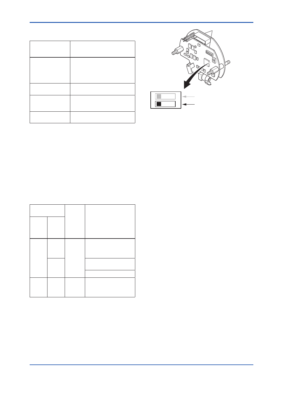
F0702.ai
Amplifier Assembly
SIMULATE_ENABLE switch
1
2
O
N
O
N
"ON" : Write lock enable
WRITE LOCK
Figure 7.3
Write lock Switch