Yokogawa EJX930A User Manual
Page 20
<2. Handling Cautions>
2-9
IM 01C25T02-01E
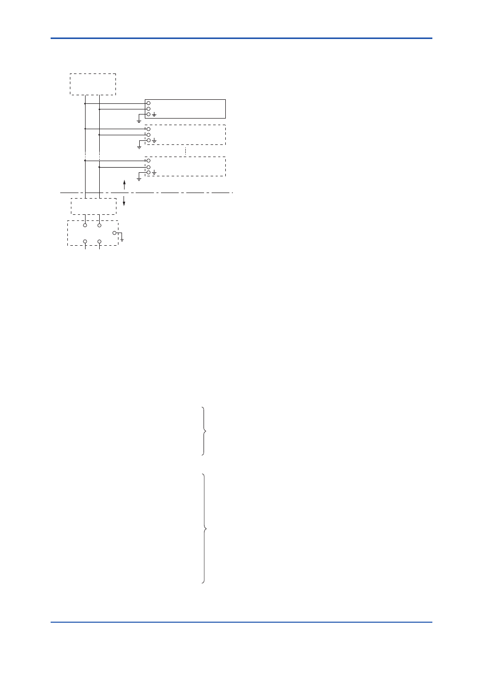
Note 6. Installation Instructions
Non-Hazardous Location
Hazardous Location
F0207.ai
Terminator
Safety Barrier
Transmitter
Pressure
Transmitter
Transmitter
+
−
+
−
+
−
Terminator
+
−
+
−
[Installation Diagram]
SUPPLY
• In the rating 1(*1), the output current of the
barrier must be limited by a resistor ‘Ra’ such
that Io = Uo/Ra.
• In the rating 2(*2), the output of the barrier
must be the characteristics of the trapezoid
or the rectangle and this transmitter can be
connected to Fieldbus equipment which are
in according to the FISCO model.
• The terminators may be built in by a barrier.
• More than one transmitter may be connected
to the power supply line.
• The terminator and the safety barrier shall be
certified.
Electrical data:
Maximum Input Voltage Ui: 24 V
*1:
Rating 1
Maximum Input Current Ii: 250 mA
Maximum Input Power Pi: 1.2 W
Maximum Internal Capacitance Ci: 3.52 nF
Maximum Internal Inductance Li: 0 μH
or
Maximum Input Voltage Ui: 17.5 V
*2:
Rating 2
Maximum Input Current Ii: 380 mA
Maximum Input Power Pi: 5.32 W
Maximum Internal Capacitance Ci: 3.52 nF
Maximum Internal Inductance Li: 0 μH
or
Maximum Input Voltage Ui: 17.5 V
Maximum Input Current Ii: 460 mA
Maximum Input Power Pi: 5.32 W
Maximum Internal Capacitance Ci: 3.52 nF
Maximum Internal Inductance Li: 0 μH
b. ATEX Flameproof Type
Caution for ATEX flameproof type
Note 1. The transmitters with optional code /KF22
for potentially explosive atmospheres:
• No. KEMA 07ATEX0109X
• Applicable Standard:
EN 60079-0:2009, EN 60079-1:2007,
EN 60079-31:2009
• Type of Protection and Marking Code:
Ex d IIC T6...T4Gb, Ex tb IIIC T85°C Db
• Group: II
• Category: 2G, 2D
• Enclosure: IP66 / IP67
• Temperature Class for gas-proof:
T6, T5, and T4
• Ambient Temperature for gas-proof:
–50 to 75°C (T6), –50 to 80°C (T5),
and –50 to 75°C (T4)
• Maximum Process Temperature (Tp.) for
gas-proof:
85°C (T6), 100°C (T5), and 120°C (T4)
• Maximum Surface Temperature for dust-
proof:
T85°C (Tamb.: –30* to 75°C, Tp.: 85°C)
* –15°C when /HE is specified.
Note 2. Electrical Data
• Supply voltage: 32 V dc max.
Output current: 15 mA dc
Note 3. Installation
• All wiring shall comply with local installation
requirements.
• The cable entry devices shall be of a certified
flameproof type, suitable for the conditions of
use.
Note 4. Operation
• Keep the “WARNING” label attached to the
transmitter.
WARNING: AFTER DE-ENERGIZING,
DELAY 5 MINUTES BEFORE OPENING.
WHEN THE AMBIENT TEMP.≥65°C, USE
HEAT-RESISTING CABLES≥90°C.
• Take care not to generate mechanical
sparking when accessing the instrument and
peripheral devices in hazardous location.
Note 5. Special Conditions for Safe Use