2 host setting, Host setting -2, Important – Yokogawa EJX930A User Manual
Page 27
<4. Getting Started>
4-2
IM 01C25T02-01E
NOTE
No CHECK terminal is used for Fieldbus
communication transmitter. Do not connect the
field indicator and check meter.
Before using a Fieldbus configuration tool other
than the existing host, confirm it does not affect the
loop functionality in which all devices are already
installed in operation. Disconnect the relevant
control loop from the bus if necessary.
IMPORTANT
Connecting a Fieldbus configuration tool
to a loop with its existing host may cause
communication data scrambling resulting in a
functional disorder or a system failure.
4.2 Host Setting
To activate Fieldbus, the following settings are
required for the host.
IMPORTANT
Do not turn off the power immediately after
setting. When the parameters are saved to the
EEPROM, the redundant processing is executed
for an improvement of reliability. If the power
is turned off within 60 seconds after setting is
made, the modified parameters are not saved
and the settings may return to the original values.
Table 4.1
Operation Parameters
Symbol
Parameter
Description and Settings
V (ST)
Slot-Time
Indicates the time
necessary for immediate
reply of the device. Unit of
time is in octets (256 μs).
Set maximum
specification for all
devices. For the
transmitter, set a value of
4 or greater.
V (MID)
Minimum-Inter-
PDU-Delay
Minimum value of
communication data
intervals. Unit of time is in
octets (256 μs). Set the
maximum specification
for all devices. For the
transmitter, set a value of
4 or greater.
V (MRD) Maximum-
Reply-Delay
The worst case time
elapsed until a reply is
recorded. The unit is
Slot-time; set the value
so that V (MRD) × V
(ST) is the maximum
value of the specification
for all devices. For the
transmitter, the setting
must be a value of 12 or
greater.
V (FUN) First-Unpolled-
Node
Indicate the address next
to the address range used
by the host. Set 0 × 15 or
greater.
V (NUN) Number-of-
consecutive-
Unpolled-Node
Unused address range.
Not used
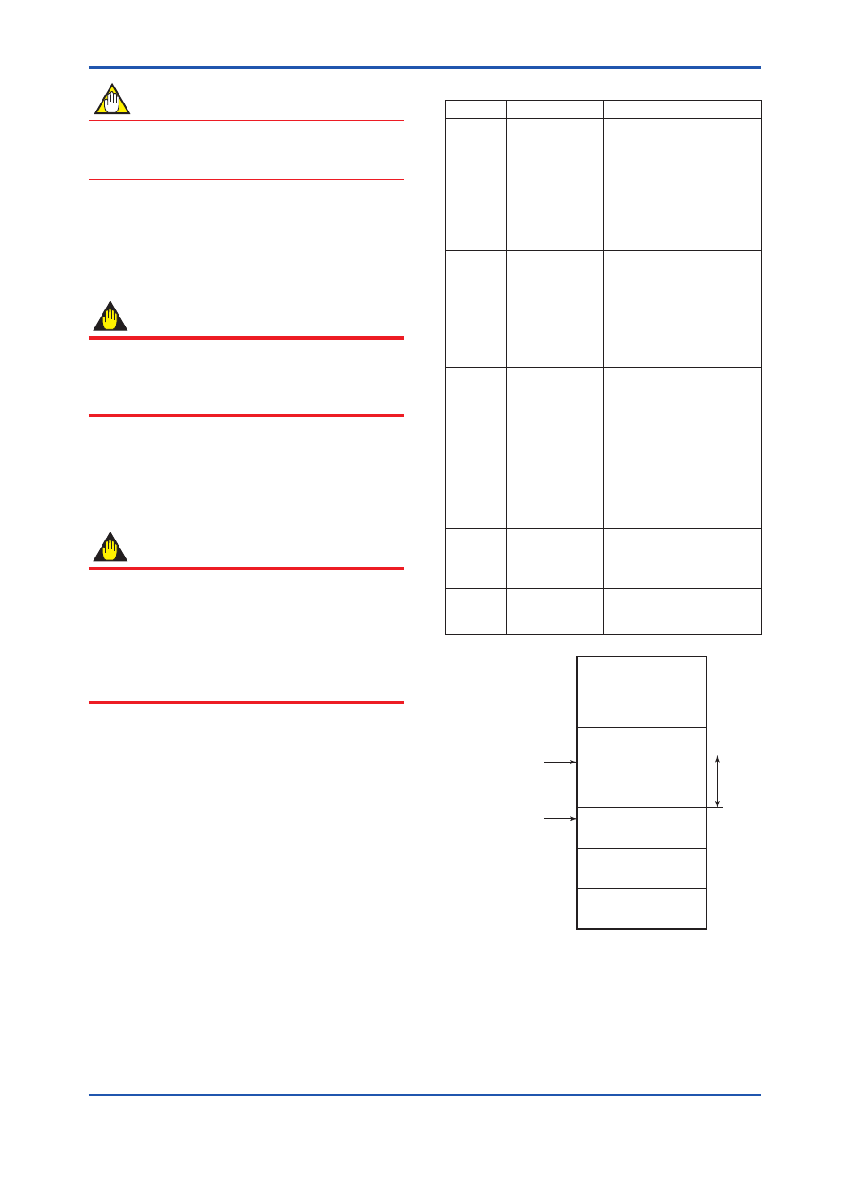
0x00
0xF7
0xF8
0x0F
0x10
0x13
0x14
0xFB
0xFC
0xFF
V(FUN)
V(FUN)+V(NUN)
LM device
Bridge device
Unused
V(NUN)
BASIC device
Default address
Portable device address
F0403.ai
Note 1: Bridge device: A linking device which brings data
from one or more H1 networks.
Note 2: LM device: with bus control function (Link Master
function).
Note 3: BASIC device: without bus control function.
Figure 4.2
Available Address Range