3 lcd transducer block, Lcd transducer block -8 – Yokogawa EJX930A User Manual
Page 72
<9. Parameter Lists>
9-8
IM 01C25T02-01E
Relative
Index Index
Parameter Name
Factory Default Write
Mode
Explanation
102
2102
FLG_TEMP_L_LIM
-50
—
Used for Heat trace monitoring. Refer to A8.3.6.
103
2103
FLG_TEMP_ALM
—
Used for Heat trace monitoring. Refer to A8.3.6.
104
2104
TEST_KEY1
—
Not used for the transmitter.
105
2105
TEST_KEY2
—
Not used for the transmitter.
106
2106
TEST_KEY3
—
Not used for the transmitter.
107
to
137
2107
to
2137
TEST_1 to TEST_31
—
Not used for the transmitter.
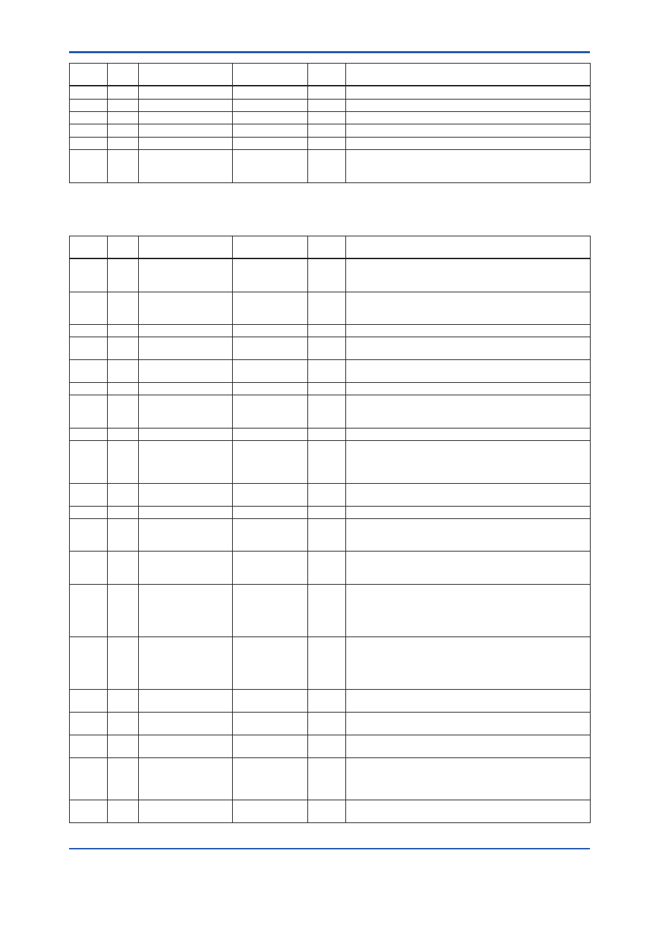
9.3 LCD Transducer Block
Relative
Index Index
Parameter Name
Factory Default Write
Mode
Explanation
0
2500
Block Header
TAG: “LTB”
Block
Tag =
O/S
Information on this block such as Block Tag, DD Revision,
Execution Time etc.
1
2501
ST_REV
—
—
The revision level of the static data associated with the function
block. The revision value will be incremented each time a static
parameter value in the block is changed.
2
2502
TAG_DESC
Null
O/S
The user description of the intended application of the block
3
2503
STRATEGY
1
O/S
The strategy field can be used to identify grouping of blocks.
This data is not checked or processed by the block.
4
2504
ALERT_KEY
1
O/S
The identification number of the plant unit. This information
may be used in the host for sorting alarms, etc.
5
2505
MODE_BLK
AUTO
O/S
The actual, target, permitted, and normal modes of the block.
6
2506
BLOCK_ERR
—
—
This parameter reflects the error status associated with
hardware or software components associated with a block. It is
a bit string, so that multiple errors may be shown.
7
2507
UPDATE_EVT
—
—
This alert is generated by any change to the static data.
8
2508
BLOCK_ALM
—
—
The block alarm is used for all configuration, hardware,
connection failure or system problems in the block. The cause
of the alert is entered in the subcode field. The first alert to
become active will set the Active status in the Status attribute.
9
2509
TRANSDUCER_
DIRECTORY
—
—
A directory that specifies the number and starting indices of the
transducers.
10
2510
TRANSDUCER_TYPE 65535 (other)
—
Identifies transducer.
11
2511
XD_ERROR
—
—
The error code in transducer.
0=No failure
19=Configuration error
12
2512
COLLECTION_
DIRECTORY
—
—
A directory that specifies the number, starting indices, and DD
Item Ids of the data collections in each transducer within a
transducer block.
13
2513
DISPLAY_SEL
DISPLAY1 ON
O/S
Selection of display1 to 4 to be shown on LCD
Bit0=1:DISPLAY1 ON
Bit1=1:DISPLAY2 ON
Bit2=1:DISPLAY3 ON
Bit3=1:DISPLAY4 ON
14
2514
INFO_SEL
UNIT ON,
PARAMETER ON
O/S
Selection of items to be displayed
Bit0=1:TAG ON
Bit1=1:PARAMETER ON
Bit2=1:UNIT ON
Bit3=1:STATUS ON
15
2515
BLOCK_TAG1
AI1
—
Block tag which includes a parameter to be displayed on
display1
16
2516
PARAMETER_SEL1
AI OUT
O/S
Selection of a parameter to be displayed on display1. Select a
parameter from Table 6.1
17
2517
DISPLAY_TAG1
Null
O/S
Name of block tag to be displayed on display1; up to six
alphanumeric plus a slash [/] and a period [.]
18
2518
UNIT_SEL1
0 (Auto)
O/S
Selection of unit to be displayed. The unit of the parameter
which is selected at PARAMETER SEL1 will be displayed
when "Auto" is selected; user-specified unit at DISPLAY UNIT1
will be displayed when "Custom" is selected.
19
2519
DISPLAY_UNIT1
Null
O/S
User specified unit to be displayed on display1, which will be
available when "Custom" is selected at UNIT SEL1.