Getting started, 1 connection of devices, Getting started -1 – Yokogawa EJX930A User Manual
Page 26: Connection of devices -1
<4. Getting Started>
4-1
IM 01C25T02-01E
4. Getting Started
Fieldbus is fully dependent upon digital
communication protocol and differs in operation
from conventional 4 to 20 mA transmission and
the BRAIN or HART communication protocol. It is
recommended that novice users use field devices
in accordance with the procedures described in this
section. The procedures assume that field devices
will be set up on a bench or in an instrument shop.
4.1 Connection of Devices
The following are required for use with Fieldbus
devices:
• Power supply:
Fieldbus requires a dedicated power supply. It
is recommended that current capacity be well
over the total value of the maximum current
consumed by all devices (including the host).
Conventional DC current cannot be used as is.
• Terminator:
Fieldbus requires two terminators. Refer to
the supplier for details of terminators that are
attached to the host.
• Field devices:
Connect the Fieldbus communication type
transmitter. Two or more transmitters or other
devices can be connected.
• Host:
Used for accessing field devices. A
dedicated host (such as DCS) is used for
an instrumentation line while dedicated
communication tools are used for experimental
purposes. For operation of the host, refer to
the instruction manual for each host. No other
details on the host are given in this manual.
• Cable:
Used for connecting devices. Refer to “Fieldbus
Technical Information” (TI 38K03A01-01E)
for details of instrumentation cabling. For
laboratory or other experimental use, a twisted
pair cable two to three meters in length with a
cross section of 0.9 mm
2
or more and a cycle
period of within 5 cm (2 inches) may be used.
Termination processing depends on the type of
device being deployed. For the transmitter, use
an M4 screw terminal claw. Some hosts require
a connector.
Refer to Yokogawa when making arrangements to
purchase the recommended equipment.
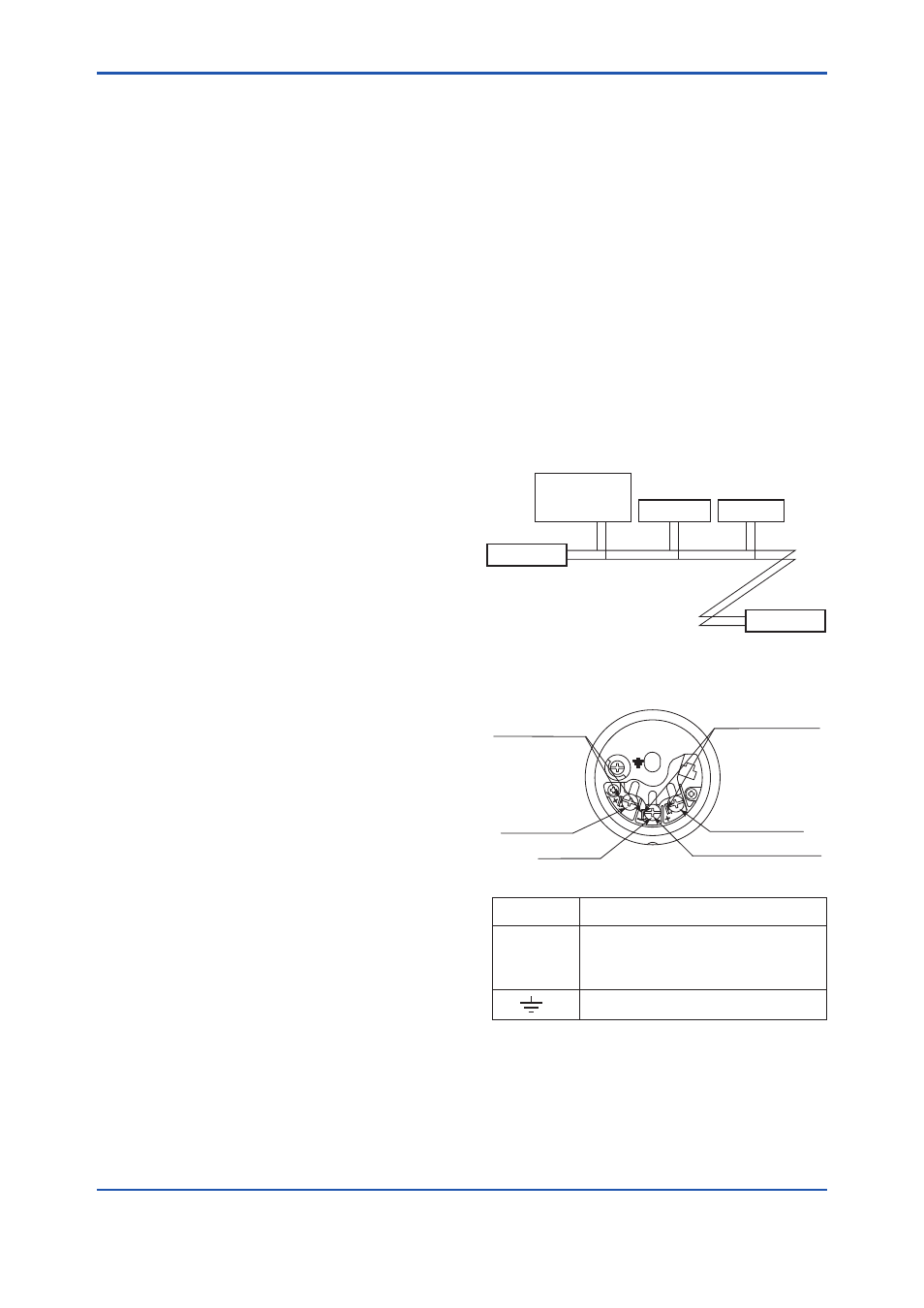
Connect the devices as shown in Figure 4.1.
Connect the terminators at both ends of the
trunk, with a minimum length of the spur laid for
connection.
The polarity of signal and power must be
maintained.
Transmitter
Fieldbus power
supply
Terminator
Terminator
HOST
F0401.ai
Figure 4.1
Cabling
SUPPLY
CHECK
or
ALARM
+
–
+
–
Power supply and output terminal
Not used for Fieldbus Communication type
Ground terminal
Communication
terminals
connection hook
*1: Not available for fieldbus communication type.
Check meter
connection hook
*1
SUPPLY +
SUPPLY –
CHECK – or ALARM –
*1
CHECK + or
ALARM +
*1
+
–
F0402.ai
Figure 4.2
Wiring Diagram