IAI America ISWA User Manual
Page 53
45
1
1. Procedure for Motor Replacement
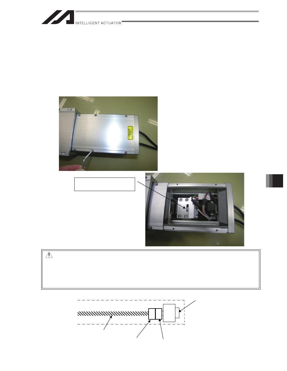
You can now see the ball screw side of the coupling.
For an actuator equipped with a brake, connect the encoder cable to the controller and turn on the power
supply to the controller.
As a next step, release the brake and move the slider to the position far enough to remove the coupling
screws on the ball screw side.
After moving the slider, deactivate the brake release, turn off the power to the controller and disconnect
the encoder cable.
The ball screw side of the
coupling is visible.
Motor unit
Coupling on the
motor side
Coupling on the
ball screw side
Ball screw
CAUTION :
x If the actuator is vertically mounted (Z axis), exercise due caution so that the slider
doesn’t fall when the brake is released.
x If you attempt to move the slider with the motor cable connected, the slider
movement will become heavy due to regenerative braking. Disconnect the motor
cable before moving the slider.