B&K Precision 2552-2559 - Manual User Manual
Page 31
31
•
“GND” Coupling: Use GND coupling to display a zero-volt
waveform. Internally, the channel input is connected to a zero-volt
reference level.
•
Fine Resolution: The vertical scale readout displays the actual
Volts/Div setting while in the fine resolution setting. Changing the
setting to coarse does not change the vertical scale until the
VOLTS/DIV control is adjusted.
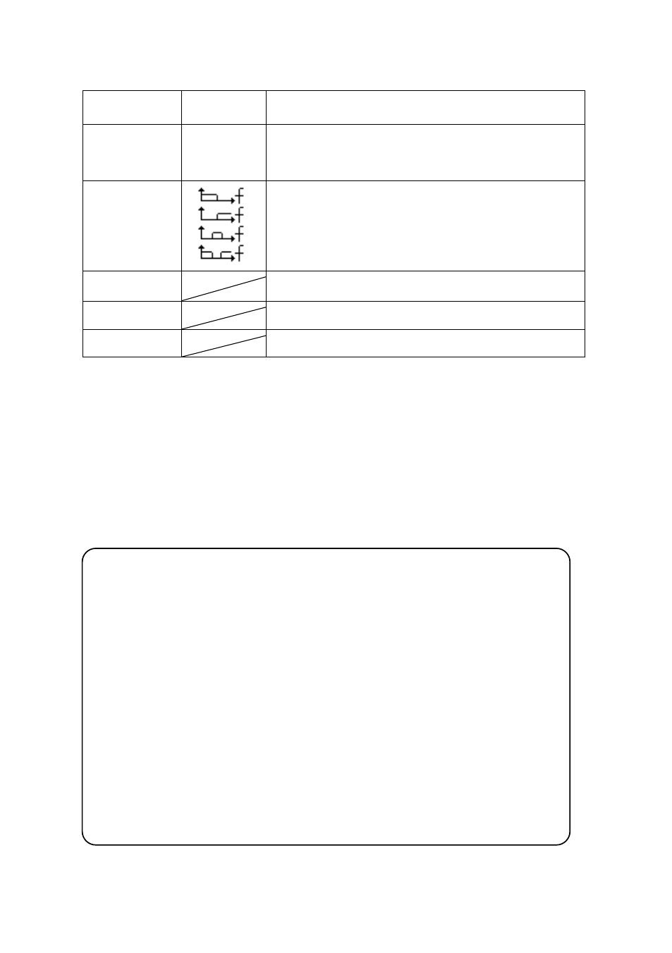
Option
Setting
Description
Filter
On
Off
Turn on the digital filter.
Turn off the digital filter.
Type
Setup as LPF (Low Pass Filter).
Setup as HPF (High Pass Filter).
Setup as BPF (Band Pass Filter).
Setup as BRF (Band Reject Filter).
Upp_limit
Turn the “Universal” knob to set upper limit.
Low_limit
Turn the “Universal” knob to set lower limit.
Return
Return to digital filter main menu.
Note: ● The oscilloscope’s vertical response rolls off slowly above its
specified bandwidth. Therefore, the FFT spectrum can show valid
frequency information higher than the oscilloscope’s bandwidth.
However, the magnitude information near or above the bandwidth
will not be accurate.
● If the channel is set to DC coupling, you can quickly measure the
DC component of the signal by simply noting its distance from the
ground symbol.
● If the channel is set to AC coupling, the DC component of the
signal is blocked allowing you to use greater sensitivity to display
the AC component of the signal.