Connectors, Onnectors – B&K Precision 2552-2559 - Manual User Manual
Page 23
23
UTILITY: Press to open the Utility menu. You can use the Utility menu to
configure oscilloscope features, such as sound, language, counter, etc. You
can also view system status and update software.
DEFAULT SETUP: Press to reset the oscilloscope’s settings to the default
factory configuration.
HELP: Enter the online help system.
AUTO: Automatically sets the oscilloscope controls to produce a usable
display of the input signals.
RUN/STOP: Continuously acquires waveforms or stops the acquisition.
Note: If waveform acquisition is stopped (using the
RUN/STOP or SINGLE button), the TIME/DIV control
expands or compresses the waveform.
SINGLE: Acquire a single waveform and then stops.
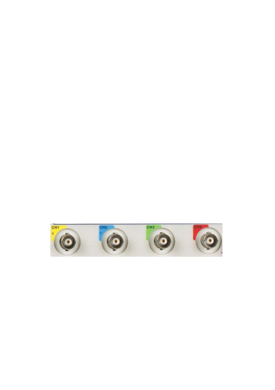
Connectors
Channel Connector (CH1, CH2, CH3, CH4): Input connectors for
waveform display.
EXT TRIG: Input connector for an external trigger source. Use the Trigger
Menu to select the “Ext” or “Ext/5” trigger source.
Probe Compensation: 1 kHz voltage probe compensation output and
ground. Use to electrically match the probe to the oscilloscope input
circuit.
Figure 12 - Connectors