0 start up and verification, continued – Alpha Technologies AlphaNet IDH4 for XM3-HP Series - Technical Manual User Manual
Page 75
75
746-257-B5-001, Rev. A1 (11/2013)
Configuring the Rx/Tx Power LED - Custom Settings
If desired, the RF Power Level ranges for the Rx/Tx PWR LED may be customized via
SNMP by adjusting the HiHi, Hi, Lo, LoLo values for the docsIfDownChannelPower and
docsIfCmStatusTxPower in the SCTE-HMS Property Table (OID:1.3.6.1.4.1.5591.1.1.1). Be
careful not to exceed the RF Input Power and Output Power range specifications of the IDH4
Series transponder.
COM - AlphaBus Communications
The COM LED indicates any data traffic being received by the IDH4 Series through the COM
(AlphaBus) port. This LED will also blink one to three times approximately every 10 seconds,
which indicates communication exists between the IDH4 Series and other connected devices,
such as a generator or additional XM3.
BAT A/B - Battery Strings A & B
The LED indicator remains ON solid when the battery string wiring harness is correctly connected
to the batteries and the Bat A/B connector on the IDH4 and IDH4X Series.
BAT C/D - Battery Strings C & D
The LED indicator remains ON solid when the battery string wiring harness is correctly connected
to the batteries and the Bat C/D connector on the IDH4X.
9.3.2 Resetting the Transponder
Should the need arise to reset the transponder locally, such as in the case of adding additional
power supplies, a generator, or carrying out maintenance activities, do the following:
Press and hold the reset button (RST) for approximately three (3) seconds. Release the button.
The transponder will perform its power up sequence. A pen or similar tool may be required to
depress the small reset button.
9.4
Verifying Communications via the Headend
Using SNMP, check connectivity by verifying power supply data by doing the following:
• With a MIB browser check power supply data in the psIdent MIB branch (1.3.6.1.4.1.5591.1) of the
SCTE-HMS tree.
• With network management software, verify the IDH4 Series has been identified and is reporting data
correctly.
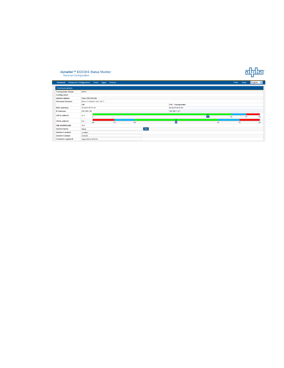
Fig. 9-5, IDH4 Series Web Page, RF Power Level Indicators
9.3.1 Detailed LED Descriptions, continued
Rx/Tx Power, continued
The current RF level status for both the Rx and Tx will be displayed on the colored scale
highlighted in black, providing verification of modem RF power levels. Refer to the figure below
for an example of the RF power level indicator bars on the Web page.
9.0 Start Up and Verification, continued