0 overview, 1 system diagram – Alpha Technologies AlphaNet IDH4 for XM3-HP Series - Technical Manual User Manual
Page 10
10
746-257-B5-001, Rev. A1 (11/2013)
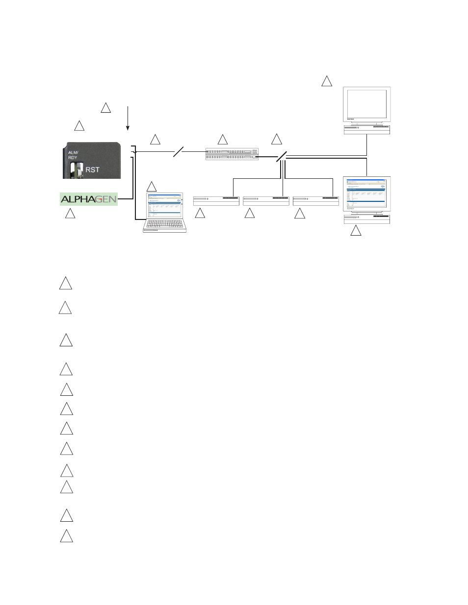
All power supply data is stored in the power supply inverter module's class information base (CIB) tables in the power supply.
This data is accessible directly via the power supply’s smart display (see the power supply’s technical manual for details).
The CIB tables are the source of the transponder’s data.
The IDH4 Series contains both SCTE-HMS Management Information Base (MIBs) and the proprietary Alpha MIB tables. The
SCTE-HMS MIBs are industry standard MIB tables that store power supply, battery and generator data from the CIB tables
(See
Section 7.0, Data Management). The Alpha MIB contains all the data of the SCTE-HMS MIBs, additional power supply
settings and values, and IDH4 Series configuration values.
An external generator or additional power supplies may be connected through the COM (AlphaBus, available only on the
IDH4X) port permitting monitoring locally through the Ethernet connector or remotely via the Web page or SNMP-based
Network Management System.
Power supply and transponder parameters can be monitored and set locally using a personal computer and a standard
Ethernet cable.
The IDH4 Series transmits data via its cable modem directly over the Coax or Hybrid Fiber Coax network.
The Cable Modem Termination System (CMTS) is the bridge between the cable network and the TCP/IP network. The IDH4
Series’ cable modem communicates directly with the CMTS.
The Dynamic Host Control Protocol (DHCP) server needs to be provisioned with the IDH4’s cable modem CM MAC address
and the MAC address needs to be assigned a DOCSIS Configuration File.
The DOCSIS Configuration File and firmware files should be available in the Root Directory of the Trivial File Transfer
Protocol (TFTP) Server.
The Time of Day (TOD) Server provides the cable modem with the current date and time via the SNTP protocol.
A Network Management System (NMS) or MIB Browser allows remote monitoring of parameter values and changing of
settings in SNMP MIB tables. SCTE-HMS and Alpha MIBs must be installed in the browser. Alarms and traps can be set and
monitored.
The power supply and generator data may be accessed remotely through the transponder's Web page by placing its IP
address into a standard Internet Web browser.
The following ports of the Transmission Control Protocol/Internet Protocol network must be opened: 161=SNMP, 162=SNMP,
Traps, 69=TFTP, 80=HTTP.
Power Supply
Local Computer
Coax/HFC Network
CMTS
TCP/IP Network
SNMP-based Network Management System
DHCP Server
1
IDH4
Series
2
External Generator
3
4
5
6
12
TFTP Server
TOD Server
Web Browser
7
8
9
10
11
1
2
3
4
5
6
7
8
9
10
11
Fig. 2-1, Representative System Arrangement
2.0 Overview
2.1
System Diagram
12