0 start up and verification, 1 initial start up and local verification, Fig. 9-1, xm3-hp smart display screens – Alpha Technologies AlphaNet IDH4 for XM3-HP Series - Technical Manual User Manual
Page 70
70
746-257-B5-001, Rev. A1 (11/2013)
9.1
Initial Start Up and Local Verification
To confirm successful hardware installation before leaving the installation site, verify network connectivity and
correct hardware interconnection.
To Verify Network Connectivity:
The DS and REG LEDs on the front of the IDH4 Series should be ON solid green. This indicates successful
registration with the headend. In addition, the RF LED should also be ON solid green indicating proper RF
power levels and the ALM/RDY LED should be blinking green for normal operation.
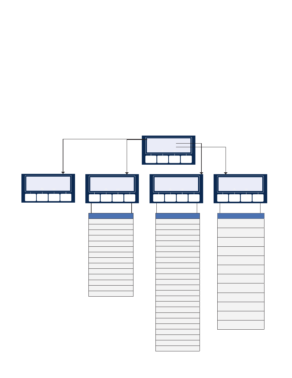
With the IDH4 Series used in conjunction with the XM3-HP power supply, network connectivity can be verified
via the COMM menu on the XM3-HP Smart Display. The following provides a list of parameters available on
the XM3-HP Smart Display populated with sample values. Important communication parameters such as the
cable modem IP address, upstream and downstream power levels can be viewed on the COMM - GENERAL
menu selection to confirm network connectivity. If no RF power is detected at the RF connector, a COMM -
FAULT menu will populate in the COMM menu.
9.0 Start Up and Verification
Fig. 9-1, XM3-HP Smart Display Screens
COMM - GENERAL
COMM - EXTENDED
COMM - DIAGNOSITCS
ENTER
ESC
ESC
COMM - GENERAL
CM MAC ADDRESS
00:90:EA:A0:04:99
ESC
COMM - EXTENDED
IDH4 MODEL/CONFIG
IDH4X CW - 8B
ESC
COMM - DIAGNOSTICS
CABLE MODEM STATUS
Operational
ESC
COMM - EXTENDED
IDH4 MODEL/CONFIG
DSM3X CW-8B
IDH4 FIRMWARE VERSION
4.4.9.0_03.02_NA
SYSTEM NAME
ABC123 CABLE
SYSTEM CONTACT
JOHN DOE
SYSTEM LOCATION
123 BAKERVIEW
COMMON LOGICAL ID
12345-3767 ALPHAWAY
DOCSIS CONFIG FILE
ALPHA_IDH4.CM
IDH4 SERIAL NUMBER
A00499
SYSTEM DEVICES 3/7**
IPU-1 SAG-1 DOC-1
SYSTEM DEVICES 6/7**
XM3-1 APP-1 BTQ-1
SYSTEM DEVICES 7/7**
UTL-1
CABLEWARE SERVER IP*
192.168.200.151
COMM GENERAL
CM MAC ADDRESS
00:90:EA:A0:04:99
CM IP ADDRESS
192.196.203.101
CPE MAC ADDRESS*
00:90:EA:A0:05:01
CPE IP ADDRESS*
192.168.200.100
CM RECEIVE POWER
-12.9dBmV
CM TRANSMIT POWER
34.5dBmV
DOWNSTREAM SNR
33.8dB
COMM - DIAGNOSTICS
CABLE MODEM STATUS
OPERATIONAL
SYSTEM UPTIME
3 DAYS 05H:16M:59S
DOWNSTREAM FREQUENCY
300.000 MHZ
DOWN MODULATION TYPE
256 QAM
UPSTREAM FREQUENCY
15.000 MHZ
T3 TIMEOUTS
80360
T4 TIMEOUTS
51
CODEWORD ERROR RATIO
8.20%
MICROREFLECTIONS
-5 DBC
CM RESETS
10
CM LOST SYNCS
5
LAST SNMP QUERY
Date/Time
COMM - FAULT
RF POWER LEVEL FAULT
SEE GENERAL MENU
ESC
*NOTE: Some menu items may not appear depending on
the options installed.
**NOTE: System Device menu items are internal Alpha
diagnostic codes. The System Devices menu items will
populate based on the option cards (SAG, APP, DOC)
installed and the number of external devices added to a
power system such a s multiple XM3s and/or AlphaGen.