Test the system – Extron Electronics PoleVault Digital Switcher Systems PVS 405D User Manual
Page 69
3. Test the System.
a. Connect all the input devices (PC, DVD,
document camera, and, where desired, LAN
cables, and so forth) to the transmitters and
power up the input devices. Check that power
and signal are present at the transmitters. The
LEDs light red when only power is present
and light green when power and a signal are
present.
b. At the MLC 104 IP Plus, turn on the Display.
Once the the projector is powered up, check
with an active video source (PC or DVD) that a
good image is shown on screen.
NOTE: If the display does not turn on,
check the MLC controller configuration
and wiring.
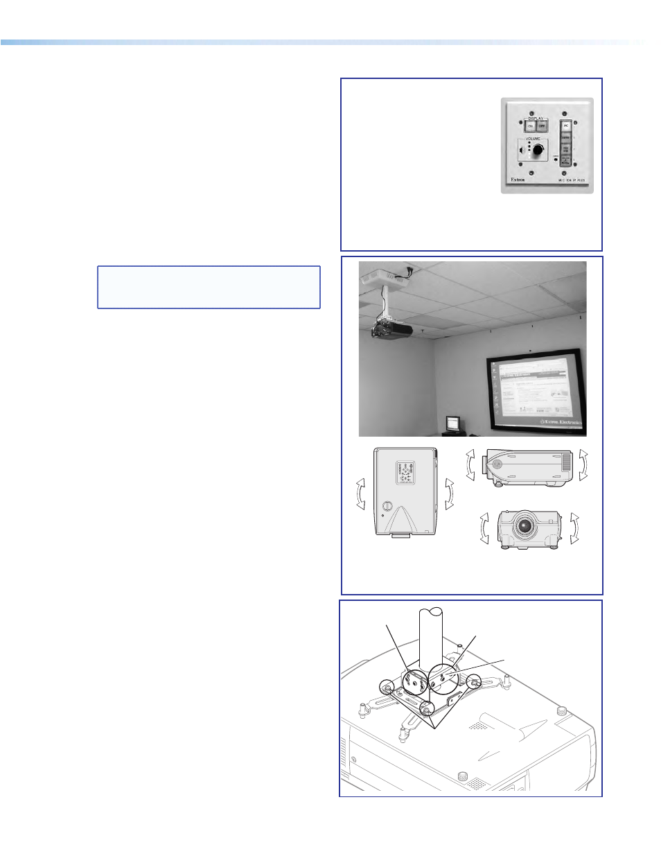
c. Properly align and adjust projector mounting
settings as follows:
•
Adjust the rotation (yaw) by turning the unit
on the projector pole. Secure the location by
tightening the two set screws on the UPB
mount plate to the pole (see below right).
•
Loosen all pivot screws and adjust the vertical
angle (pitch) of the projector. Lock down the
four adjustment screws.
•
Adjust the horizontal tilt (roll) of the projector.
Lock down all the remaining adjustment and
pivot screws.
•
Adjust the image settings on the projector
(zoom, focus, keystone, brightness, contrast,
and so on). See the projector user manual.
Vertical
Angle Adjustment
and Pivot
Point Screws
Horizontal Angle
Adjustment and
Pivot Point Screws
Adjuster
Plate Locking Screws (4)
Tighten these 2 set screws
(one each side) to lock the
UPB onto the pole.
ñ
Check that an image is present, and
adjust as needed.
Ö
Connect and turn on the input devices,
and turn on the display at the MLC.
Pitch/Vertical Angle
Yaw/Rotation
Roll/Tilt
PoleVault Digital Systems • Installation — Stage 5 (Configuration)
63