D1. remove the device mounting plate, From the access door, D2. remove ceiling tile and install – Extron Electronics PoleVault Digital Switcher Systems PVS 405D User Manual
Page 59: Suspension cables
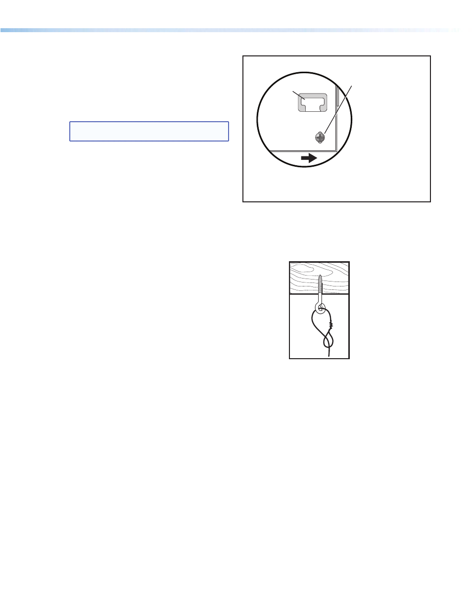
a. Remove this screw on
the right and left sides
of the mounting plate.
b. Swing the mounting plate out from the door frame
and slide the plate to the right, off the hinge pins.
Bottom of Door
(inside right
corner view)
Door Tether “T”
D1. Remove the Device Mounting Plate from
the Access Door.
a. Open the access door and unscrew the two
Phillips screws that are located in the bottom
corners of the plate (left and right sides), near
the door latches and door tether “T.”
NOTE: Do not remove any of the screws located
below the hinges.
b. Swing the bottom of the plate up to separate it
from the door frame, then slide the plate to the
right until it becomes free of the hinge pins on
the door frame.
Retain the device mounting plate for later use
(see step D6).
D2. Remove Ceiling Tile and Install
Suspension Cables.
For threaded rod installation see step D3, steps a-c,
at the top of page 55.
a. At the location where the PVM 220 is to be
installed, remove the ceiling tile and mark the
T-grid for that tile then remove the adjacent tiles
to make working on the grid easier.
b. At an approximate angle of 10 degrees out
from each corner of where the PVM 220 will
be installed, mark and drill four holes in the
structural ceiling for the suspension cable
anchors.
c. Screw a lag eye bolt (or an appropriate anchor)
into each hole.
d. Thread the looped end of the suspension cable
though the bolt eyehole, pass the rest of the
cable through the loop and tighten.
Allow each cable to hang down.
Remove the Access Door.
Secure using lag bolts.
PoleVault Digital Systems • Installation — Stage 4 (PVM 220 and PVS 405D)
53