D9. cable the switcher, D8. install the device mounting plate onto, The access door – Extron Electronics PoleVault Digital Switcher Systems PVS 405D User Manual
Page 64: Cable the switcher
PVS
40
5SA
IP
PO
LEV
AU
LT S
WIT
CH
ER
INP
UTS
AUD
IO L
EVE
L A
DJU
ST
PAGI
NG
SEN
SOR
SEN
SIT
IVIT
Y
PEA
K
NO
RM
AL
SIG
NA
L
VOIC
ELIF
T
PEAK
NO
RM
AL
SIG
NA
L
INP
UT
SEL
ECT
CO
NFI
G
R
1 2
3 4
5
A
U
X
A
U
D
IO
E
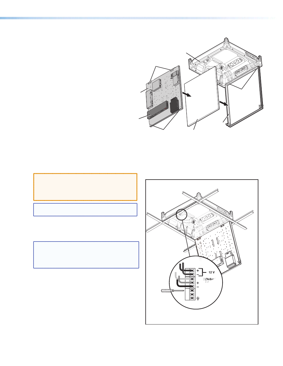
Ceiling Tile
Insert
Door Frame
Device Mounting
Plate (with devices
installed)
PVM 220 Enclosure
PoleVault
Switcher
(front panel
facing down)
Device Mounting
Plate Screws
Device Mounting
Plate Hinge Pins
Device Mounting
Plate Hinges
D8. Install the Device Mounting Plate onto
the Access Door.
To fit the mounting plate and devices on the
access door:
a. Align and slide the device mounting plate onto
the two hinge pins located at the top of the
door frame.
b. Secure the plate into place with
the two mounting plate screws,
located at the bottom of the
door frame.
D9. Cable the Switcher.
a. Connect the cables to the switcher as shown
on pages 43.
CAUTION:
The signal transmission method is
specific for PVS 405D switcher working with PVT
digital wallplates.
DO NOT connect the input
ports to an MTP, DTP, or XTP system or to an LAN
or data transmission system.
NOTE: For cable connections to optional devices see
the relevant device guide or manual.
b. Plug in the fan controller cable to the switcher
power supply. The fan comes already pre-wired
to the controller in the enclosure.
NOTE: The fan is controlled automatically by the
internal temperature of the PVM 220. The fan can
also be turned on or off manually (see below for
wiring). Manually controlling the fan overrides the
automatic thermal control mode.
The fan can be wired to a control system for manual
On/Off as follows (see figure at right for connectors):
•
For manual On, wire a latching relay to the On
and Ground connectors on the fan controller.
•
For manual Off, wire a latching relay to the Off
and Ground connectors on the fan controller.
c. Connect and dress the other device cables as
needed, providing enough slack to open and
close the access door.
12 V
TACH (Yellow)
FAN (Red)
FAN (Black)
ON
OFF
GROUND
Install the Mounting Plate onto the Access Door.
Wire the fan controller for manual on and off.
PoleVault Digital Systems • Installation — Stage 4 (PVM 220 and PVS 405D)
58