C4. cable the switcher, And projector – Extron Electronics PoleVault Digital Switcher Systems PVS 405D User Manual
Page 56
iii.
Run the cables through the raceway or conduit
to the USFM 100.
C4. Cable the Switcher.
Connect the cables to the switcher as shown on
pages 43.
NOTE: If using a device other than a PVS 405D (for
example, PVS 305SA IP), refer to the specific device
guide for details.
CAUTION: The WallVault signal transmission
method is specific for PVS 405D switcher
working with PVT digital wallplates.
DO NOT connect the input ports to an MTP,
DTP, or XTP system, or to an LAN or data
transmission system.
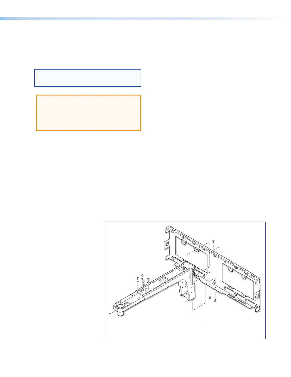
C5. Attach the Boom Arm, Power Supply, and
Projector.
a. Hook the boom arm over the top rail on the
base plate so that the tab on the arm
(see figure below) is against the rail.
Secure the arm at the bottom with the two
supplied (10-32 x 3/8 inch) pan head screws
and washers, and at the top with the single
¼-28 x ¾ inch screw.
USFM 100 Base Plate.
Phillips
Pan Head Screws
Screw
Set Screw
Screws
and Washers
PoleVault Digital Systems • Installation — Stage 4 (USFM 100 and PVS 405D)
50
- AVTrac Corner Cut Solution (2 pages)
- AVTrac Demonstration Kit (2 pages)
- AVTRac End Ramp and Cable Pass-Through Kits (1 page)
- AVTrac Extension Kit (15 pages)
- 1U and 2U Rack Plate (1 page)
- Under-Desk Mounting Bracket (1 page)
- AAP Wiring Guide 68-1054-01 (1 page)
- AAP Wiring Guide 68-1052-01 (1 page)
- AAP Wiring Guide (XLR connectors) (1 page)
- AAP 314 (1 page)
- AAP 301 (1 page)
- AAP Wiring Guide 68-1055-01 (1 page)
- AAP Wiring Guide 68-1058-01 (1 page)
- AAP Wiring Guide 68-1059-01 (1 page)
- AAP-MAAP Rev. A (1 page)
- AAP-MAAP Rev. D (1 page)
- MD Floor Box AAP Bracket Kit AAP 100 MD (1 page)
- AC 100 Power Module Series (1 page)
- AAP 103 Extron Ackerman AKM UK Faceplate Kit (1 page)
- ACMP 100 (2 pages)
- Active Audio AAP (1 page)
- AKM UK Series (4 pages)
- Audio AAP Wiring Guide (1 page)
- Audio Connector Rev. A (2 pages)
- Audio Connector Rev. G (1 page)
- AVTrac Extra Channel Kit (2 pages)
- AVTrac Raceway Transition (2 pages)
- AVTrac Retrofit Transition Adapter (2 pages)
- AVTrac Trim Ring-Rough-in Adapter (2 pages)
- AVTrac Above Floor (1 page)
- BB 1 (2 pages)
- BB 1000M (2 pages)
- BB 700M (2 pages)
- BB 710M (2 pages)
- Blank Rack Panel (1 page)
- BNC to 15-Pin HD (1 page)
- BNC-5 RC Termination (1 page)
- Cable Cubby 1200 (6 pages)
- Cable Cubby 200 (18 pages)
- Cable Cubby 300C (27 pages)
- Cable Cubby 500 (6 pages)
- Flexible Conduit Kit (2 pages)
- Cable Cubby Lid and Trim Ring Replacement Kit (for 300C, 300S, 600, 800) (1 page)
- Cable Cubby Setup Guide (4 pages)
- Cable Cubby Single Space AAP Bracket Kit (1 page)