Stage 4, The pvs 405d digital switcher – Extron Electronics PoleVault Digital Switcher Systems PVS 405D User Manual
Page 45
Stage 4:
Installing the Switcher
Mounting System and
the PVS 405D
Stage 4 Involves installing the switcher mounting system and the PVS 405D Digital Switcher.
This stage is divided into four sections based on the system type. Each system mounts the PVS 405D
switcher and associated power supply using a specific mounting kit.
A. PoleVault System (using the PMK 560 Pole Mount Kit)
B. WallVault Wall Mount System (using the WMK 160 Wall Mount Kit)
C. WallVault Short Throw System (using the USFM 100 Short Throw Wall Mount Kit)
D. PlenumVault System (using the PVM 220 PlenumVault Mount Kit)
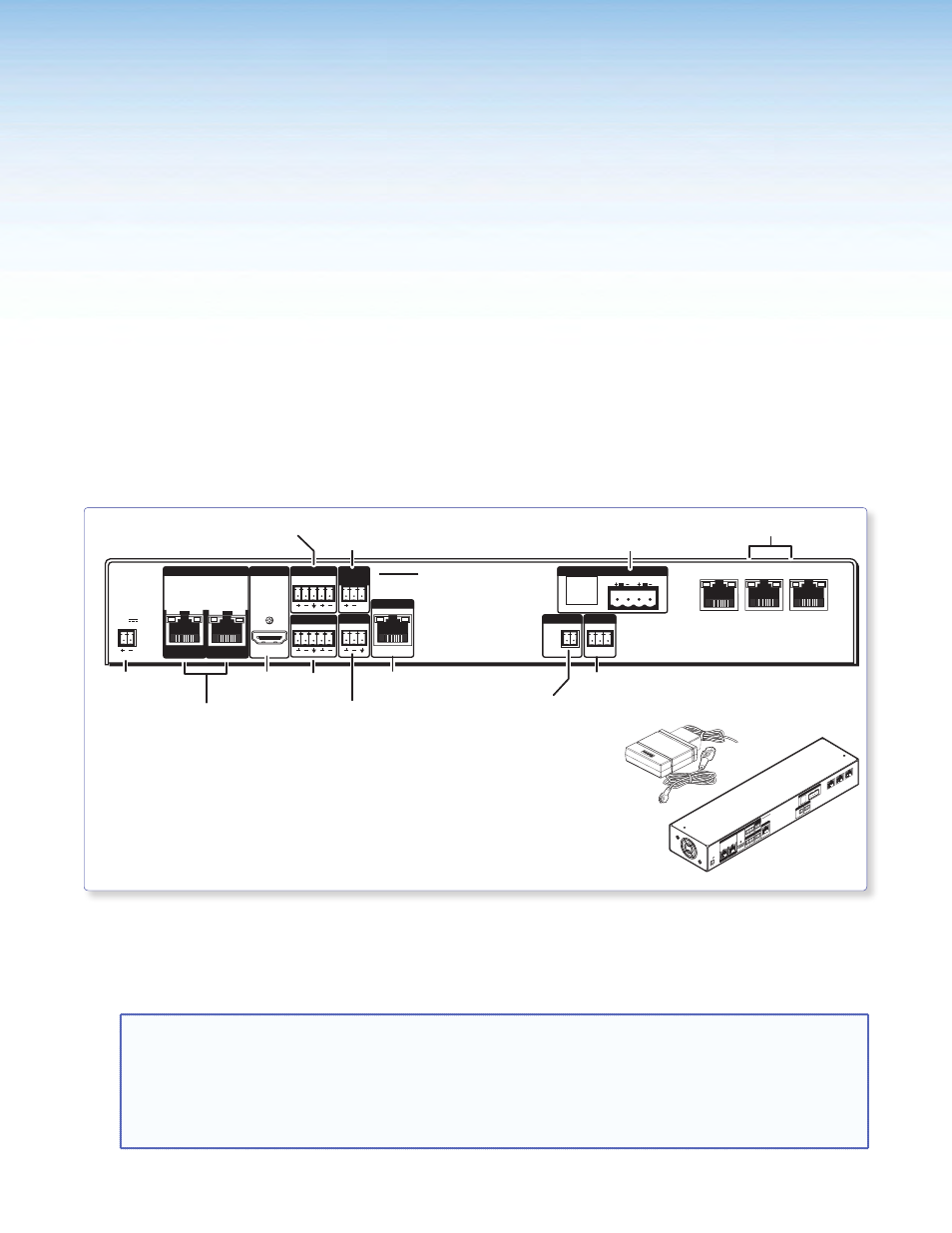
The PVS 405D Digital Switcher
.
L
R
DO NOT
GROUND
OR SHORT
SPEAKER
OUTPUTS
4/8
Ω
3A MAX
POWER
12V
HDMI
1/2
SIG
LINK
SIG
LINK
3/4
INPUTS
OUTPUT
AUDIO OUT
PVS 405D
AMPLIFIED AUDIO OUT
PAGING
SENSOR
PVT IN
PVT IN
L
R
AUX
OVER PVT REMOTE
VOICELIFT
LAN 1
LAN 2
LAN 3
INPUT 5
+V
L
R
RS-232
Tx Rx
IR
S G
G
HDMI/RGB Video and Audio
Inputs (1-4) from
PVT SW HDMI RGB D
Power Supply
Connector
Aux
Input
HDMI
Output
Speaker
Output
Aux Audio
Input 5
RS-232
Control Port
VoiceLift
Receiver Port
Lineout
Output
Paging Sensor
Port
3-Port 10/100
Ethernet Switch
IR Control
Input
Rear View
•
Where it goes: PVS 405D and power supply install into a mounting
enclosure.
•
What it does: Receives input video and audio signals from AV source
input wall plates. Outputs and switches the video and
audio signals to a display device (such as a projector or
flat screen display) and ceiling speakers.
L
R
DO NOT
GROUND
OR SHOR
T
SPEAKER
OUTPUTS
4/8
Ω
3A MAX
POWER
12V
HDMI
1/2
SIG
LINK
SIG
LINK
3/4
INPUTS
OUTPUT
AUDIO OUT
PVS 405D
AMPLIFIED AUDIO OUT
PAGING
SENSOR
PVT IN
PVT IN
L
R
AUX
OVER PVT
REMOTE
VOICELIFT
LAN 1
LAN 2
LAN 3
INPUT 5
+V
L
R
RS-232
Tx
Rx
IR
S
G
G
For installation of the PMK 560 for the PoleVault system, start at page 40.
For installation of the WMK 160 for the WallVault Wall Mount system, start at page 44.
For installation of the USFM 100 for the WallVault Short Throw system, start at page 47.
For installation of the PVM 220 for the PlenumVault system, start at page 52.
NOTES:
•
The installation must conform to national and local building and electrical codes, and UL requirements.
See the device user guide for details.
•
The included power supply
MUST NOT be installed in wall cavities or similar locations.
•
Unless installing the PVM 220 (for the PlenumVault System only) the power supply
MUST NOT be
installed above the suspended ceiling.
PoleVault Digital Systems • Installation — Stage 4 (Mounting System Kit and PVS 405D)
39