Install medialink controller, Heat shrink on drain wire – Extron Electronics PoleVault Digital Switcher Systems PVS 405D User Manual
Page 38
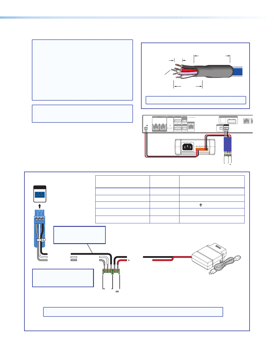
4. Install the MediaLink Controller.
TIP: Before cabling and installing the
MLC 104 IP Plus, locate the device MAC
address printed on a label on the bottom of
the controller. Write down the 12 character
alphanumeric address, (for example,
00-05-A6-03-9G-H4) and use when
configuring the IP address.
When cabling, the length of exposed wire is
critical to avoid transmission problems. Ensure
the lengths given here are adhered to when
stripping the cables for connection.
NOTE: If a drain wire is used, both ends of the
wire must be covered by heat shrink to avoid
accidental grounding.
a. Connect the MLC power and RS-232 control
cable (part number
26-626-50) as shown at
right. To do this, strip the outer jacket back
to the length appropriate to get the red and
black leads to the switcher power supply. Trim
the white/purple/drain short enough to plug
directly in to the switcher, keeping most of the
drain covered in the jacket.
MLC 104 IP Plus
right side panel
MLS and
Power
ports
PVS 405D
Remote RS-232
Port
RS-232 12V
MLS PWR
A B
Rx
Tx
GROUND
GROUND
+12V IN
G
Ground
+12 VDC input
Ground all devices.
External Power Supply
(12 VDC, 4 A)
NOTE:
If you use cable that has
a drain wire, tie the drain wire
to ground at both ends.
NOTE:
You must connect
a
ground wire between
the MLC and PVS 405D.
REMOTE
RS-232
Tx Rx G
Ground (Gnd)
Transmit (Tx)
B
G
Receive (Rx)
A
Transmit (Tx)
Receive (Rx)
B
A
Ü
Connect the MLC 104 IP Plus to the PVS 405D Switcher and Power Supply.
From MLC 104 IP Plus
terminal
Wire color
To PVS 405D terminal
A - (Rx on the MLS port)
White
(Tx on the RS-232 port)
B - (Tx on the MLS port)
Violet
(Rx on the RS-232 port)
MLS RS-232 Ground
Drain wire
Ground
Power Ground
Black
To PVS 405D Power Supply
12 V In
Red
To PVS 405D Power Supply
Wire Bared
3/16"
(5 mm)
Max.
7/8
"
(22 mm)
Heat Shrink on
Outer Jacket to
Inner Conductor
Transition
Heat Shrink on
Drain Wire
TIP: Observe wire stripping lengths.
NOTE: The MLC 104 IP Plus is powered from the PVS 405D associated power supply.
3A MAX
POWER
12V
HDMI
1/2
SIG
LINK
SIG
LINK
3/4
INPUTS
OUTPUT
AUDIO OUT
PVS 405D
PAGING
SENSOR
PVT IN
PVT IN
L
R
AUX
OVER PVT REMOTE
VOICELIFT
LAN 1
LAN 2
LAN 3
INPUT 5
+V
L
R
RS-232
Tx Rx
IR
S G
G
L
R
DO NOT
GROUND
OR SHORT
SPEAKER
OUTPUTS
4/8
Ω
AMPLIFIED AUDIO OUT
CLASS 2 WIRING
HDMI
1/2
SIG
LINK
SIG
LINK
3/4
INPUTS
OUTPUT
AUDIO OUT
PVS 405D
PAGING
SENSOR
PVT IN
PVT IN
L
R
AUX
VOICELIFT
INPUT 5
+V
L
R
MLC 104 IP Plus
right side panel
MLS and Power ports
RS-232 12V
MLS PWR
A B
Rx
Tx
GROUND
GROUND
+12V IN
OVER PVT
IR
S G
LAN 1
LAN 2
LAN 3
L
R
4/8
Ω
DO NOT
GROUND
OR SHORT
SPEAKER
OUTPUTS
AMPLIFIED AUDIO OUT
CLASS 2 WIRING
Included power supply is used for both
PVS 405D and MLC 104 IP Plus
PoleVault Digital Systems • Installation — Stage 2 (Wallplates and MLC)
32