D6. install devices onto the device mounting plate, D6. install devices onto the device mounting, Plate – Extron Electronics PoleVault Digital Switcher Systems PVS 405D User Manual
Page 63: D7. cut and install the ceiling tile in the, Access door
D6. Install Devices onto the Device Mounting
plate.
NOTE: The maximum door load is 15 lbs (6.8 kg).
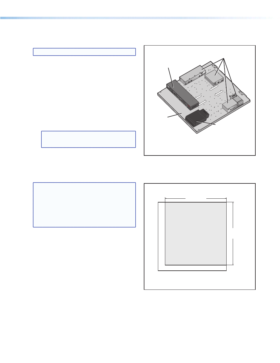
To mount the devices and accessories:
a. Carefully align the switcher with the appropriate
holes only, indicated by arrows on the mounting
plate.
b. Secure the switcher with the supplied #4-40
»
inch mounting screws, tightening each one
until snug. Do not overtighten.
c. Mount the power supply onto the device
mounting plate in the marked location (indicated
by arrows on the mounting plate), using the
supplied screws.
NOTE: Replacement power supplies must be
either the equivalent Extron power supply,
or a UL Listed NEC Class 2 power supply.
d. Mount any other approved devices following the
procedures in the supplied device guide.
D7. Cut and Install the Ceiling Tile in the
Access Door.
NOTES:
•
The door can accept a ceiling tile thicknesses
of Œ-1… inches. Check the tile thickness
before cutting.
•
If the ceiling tiles have a specific pattern
direction, ensure the overall pattern direction
is maintained when cutting and fitting the cut
tile insert into the access door.
a. Mark the dimensions (22 inches by 21.5 inches)
for the PVM 220 access door on the installation
tile and cut the tile to size.
b. With the access door open, insert the cut
ceiling tile into the door frame (see figure on
page 58).
21.5"
(54.6 cm)
22.0"
(55.9 cm)
Cut the ceiling tile to 22 x 21.5 inches
and use that part for insertion into the
access door
.
Example: 24 x 24 inch Ceiling Tile
Bottom of Door (Door Locks)
PVS
405
SA I
P
PO
LEV
AUL
T S
WIT
CH
ER
INP
UTS
AUD
IO LE
VEL
ADJ
UST
PAGI
NG
SEN
SOR
SENS
ITIV
ITY
PEA
K
NO
RM
AL
SIG
NAL
VOIC
ELIFT
PEA
K
NO
RM
AL
SIG
NAL
INP
UT
SELE
CT
CON
FIG
R
1
2
3
4
5
AUX
AUD
IO
E
Mount the PoleVault
switcher with the front
panel facing outwards
in the marked location.
Mount other optional
devices as desired.
PoleVault Switcher
Power Supply
Device
Mounting Plate
Mount the switcher, power supply, and devices
on the Mounting Plate.
Cut the ceiling tile
PoleVault Digital Systems • Installation — Stage 4 (PVM 220 and PVS 405D)
57