Conf ig, Secure the mlc 104 ip plus to the mud ring, Connections made to the mlc 104 ip plus – Extron Electronics PoleVault Digital Switcher Systems PVS 405D User Manual
Page 40: Projector, Ir control, Stp input cable, Extron mlc 104 ip plus
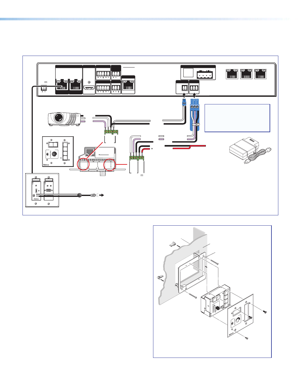
d. The connections between the MLC 104 IP Plus
and the PVS 405D switcher should look like the
figure below.
e. Sliding the cables into the opening, secure
the MLC 104 IP Plus to the mud ring with the
provided machine screws.
Extron
MLC 104 IP Plus
Wall
Mud Ring
OFF
ON
OFF
ON
CONF
IG
DISPLAY
VOLUME
1
2
3
4
MLC 104 IP Plus
ô
Secure the MLC 104 IP Plus to the mud ring.
ò
Connections made to the MLC 104 IP Plus
L
R
DO NOT
GROUND
OR SHORT
SPEAKER
OUTPUTS
4/8
Ω
3A MAX
POWER
12V
HDMI
1/2
SIG
LINK
SIG
LINK
3/4
INPUTS
OUTPUT
AUDIO OUT
PVS 405D
AMPLIFIED AUDIO OUT
PAGING
SENSOR
PVT IN
PVT IN
L
R
AUX
OVER PVT REMOTE
VOICELIFT
LAN 1
LAN 2
LAN 3
INPUT 5
+V
L
R
RS-232
Tx Rx
IR
S G
G
2
3
GR
O
UND
1
IR IN
GR
OUND
IR OU
T
CM
SC
P
GR
OUND
GR
OUND
Tx
Rx
DISPLAY
RS-232/IR
LAN
PRESS TAB WITH
TWEEKER TO REMOVE
A B
MLS PWR
RS-232 12V
DIGITAL
I/O
A B C D E
COMM LINK
+V OU
T
GR
O
UND
Tx
Rx
+12V IN
CONFIG
DISPLAY
VOLUME
MLC 104 IP PLUS
ON
VCR
DVD
PC
OFF
1
2
3
4
RS-232
MLC 104 IP Plus right side panel
MLS and Power ports
RS-232 12V
MLS PWR
A B
Rx
Tx
GROUND
GROUND
+12V IN
NOTES:
•
You must connect a
ground wire
between the MLC and PVS.
• If you use cable that has a drain
wire, tie the drain wire to ground at
both ends.
G
Ground
+12 VDC input
Ground (Gnd)
Transmit (Tx)
B
Receive (Rx)
A
Transmit (Tx)
Receive (Rx)
Tx
Rx
IR control
S
Ground
G
IR Out
Rx
Tx
Projector
GROUN
D
IR OU
T
Tx
Rx
DISPLAY
RS-232/IR
Ground
RS-232
To Supplied
PVS Switcher
Power Supply
(12 VDC, 4 A)
To Blu-ray (or similar) input device
Optional PVT Front Panel
IR Output Connection
VGA IN
AUDIO
IN
OUT
LOCAL OUT
AUDIO IN
HDMI IN
IR OUT
S
G
HDMI IN #1
RGB IN #2
IR Emitter
STP Input Cable
CLASS 2 WIRING
PoleVault Digital Systems • Installation — Stage 2 (Wallplates and MLC)
34