3 ups compartment – GE Industrial Solutions Entellisys System User Manual User Manual
Page 184
Control power and UPS configuration
184
15
15.3 UPS compartment
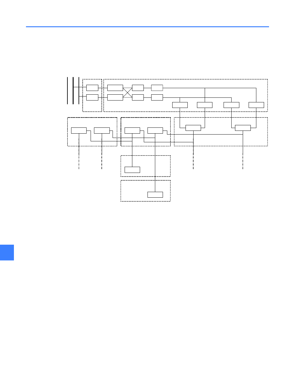
Each of the two incoming power lines from CPTs “A” and “B” connects directly to a 30 A fuse
upon entering the UPS compartment (see Figure 15-1).
Figure 15-1 Control Power & UPS overview
The system uses two throwover devices to select and transfer between the two sources to
provide power to the uninterruptible power supplies (UPSs). Each of the two lines serves as a
preferred source for one throwover device. Devices transfer from their preferred source if its
voltage drops below a specified level. Pickup and dropout voltages for the throwover devices are
set at the factory to 85% and 90% of the line voltage, respectively.
The two outputs from the throwover system are fed into a pair of 3 kVA UPSs. The UPSs are of
the on-line double-conversion type, with 120 Vac 50/60 Hz inputs and outputs. The UPSs protect
the power to the Entellisys instrumentation and circuit breaker control circuits during normal
operation, line disturbances, and complete control power source loss. The UPS system does not
provide power to the main switchgear bus nor the motor operator accessory of electrically
operated circuit breakers.
Each UPS output is split into two circuits: one for circuit breaker control circuits and the other for
instrumentation. Each of these (four) UPS-protected control power circuits is then fused to
provide protection for the downstream system. 20 A fuses protect the circuit breaker control
circuits, while 10 A fuses protect those of the Entellisys instrumentation. This architecture
protects the central Entellisys instrumentation in the event of an interruption in circuit breaker
control power.
In non-split Entellisys systems, the control power devices described above are located in a
single instrument compartment. In split systems, however, the two control power networks
(A&B) and their devices are placed in separate compartments. Thus, one input power fuse, one
UPS, one throwover device, and two output fuses are housed in each compartment.
CPT 1
CPT 2
30A Fuse
30A Fuse
83X
83X
UPS A
UPS B
20A Fuse
10A Fuse
20A Fuse
10A Fuse
Term Blk
Term Blk
Term Blk
Term Blk
Term Blk
Term Blk
Term Blk
ROOF
Stack A
ROOF
Stack B
ROOF
Stack X
INST.
COMPT.
Stack B
BREAKER
COMPARTMENT
Stack B
UPS COMPARTMENT
Stack A
Term Blk
CPU
COMPT
MAIN
BUS