4 “or” board – GE Industrial Solutions Entellisys System User Manual User Manual
Page 130
Digital I/O
130
10
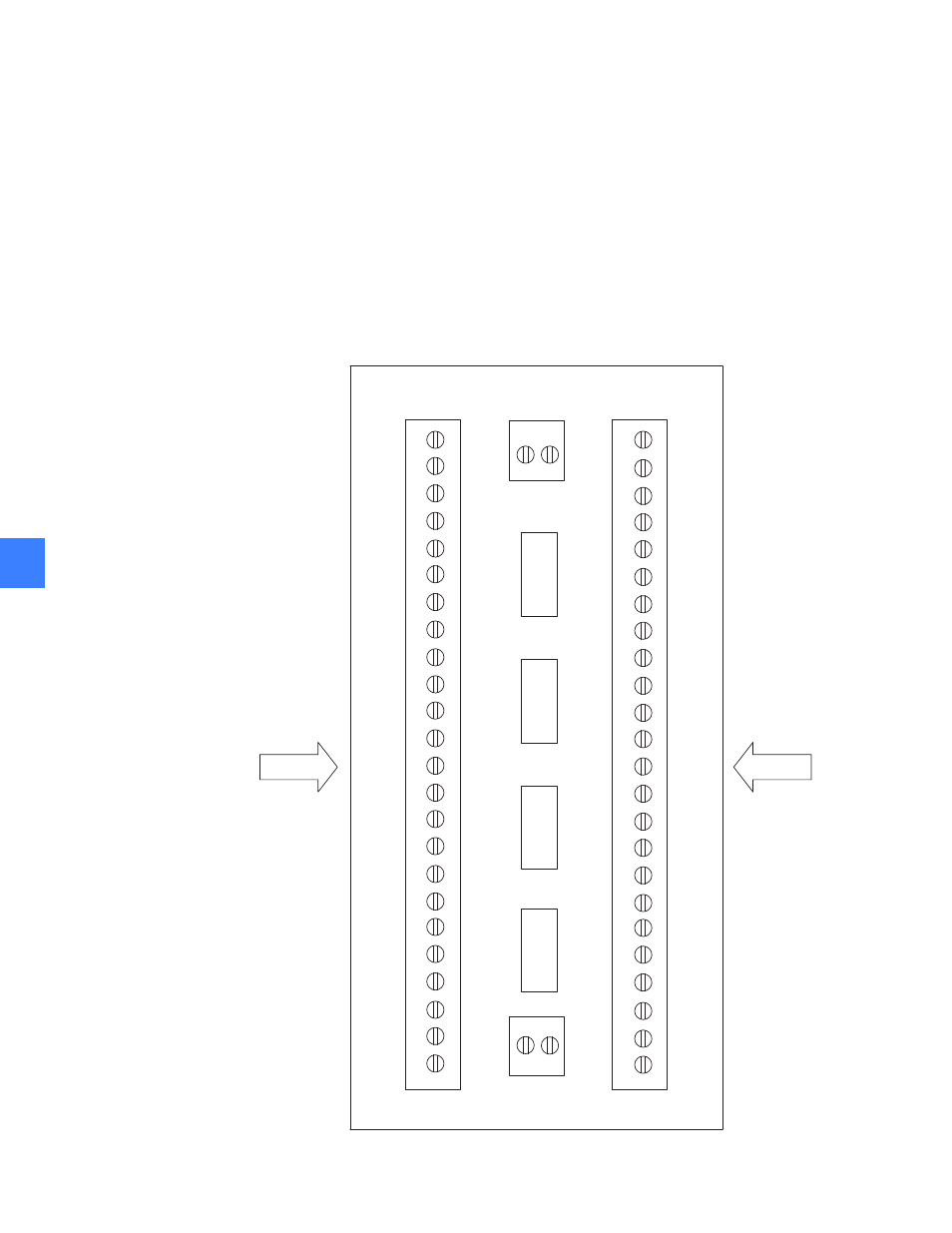
10.1.1.4 “OR” board
The “OR” board is used only in redundant configurations of discrete I/Os. In redundant
configurations, outputs on two or four discrete I/O boards (installed in two CPUs) control the
states of output relays. The “OR” board is used to electrically isolate outputs on boards. Only
outputs are connected to the “OR” board. The board logically “ORs” the signals from the outputs
of two CPUs, and the resulting signal controls output relays. There is no need to “OR” signals
from input relays. Each board can handle up to 16 outputs from each CPU. Screw terminals with
letter A designate discrete outputs from CPU A, and those with letter B designate discrete
outputs from CPU B. Connections from the outputs on terminal blocks are made in pairs. The
“OR” board takes the “OR” of each pair and outputs a single result for each pair. Depending on
the number of discrete outputs in the systems, more “OR” boards can be used.
Figure 10-3 Layout of “OR” board
1A
1B
2A
2B
3A
3B
4A
4B
5A
5B
6A
6B
7A
7B
8A
8B
9A
9B
10A
10B
11A
11B
12A
12B
13A
13B
14A
GND
OUT1
GND
OUT2
GND
OUT3
GND
OUT4
GND
OUT5
GND
OUT6
GND
OUT7
GND
OUT8
GND
OUT9
GND
OUT10
GND
OUT11
GND
OUT12
GND
OUT13
GND
GN
GN
GN
FROM TERMINAL BLOCKS
TO RELAY BLOCKS
+5V