2 switchgear installations – GE Industrial Solutions Entellisys System User Manual User Manual
Page 12
System architecture
12
1
Digital I/O is provided for customer-specific inputs and outputs. This equipment is resident in the
switchgear and is connected through the CPUs. Digital I/O and custom control schemes will run
in the CPUs if enabled.
In summary, Entellisys changes the protection paradigm from individual circuit protection to
system protection.
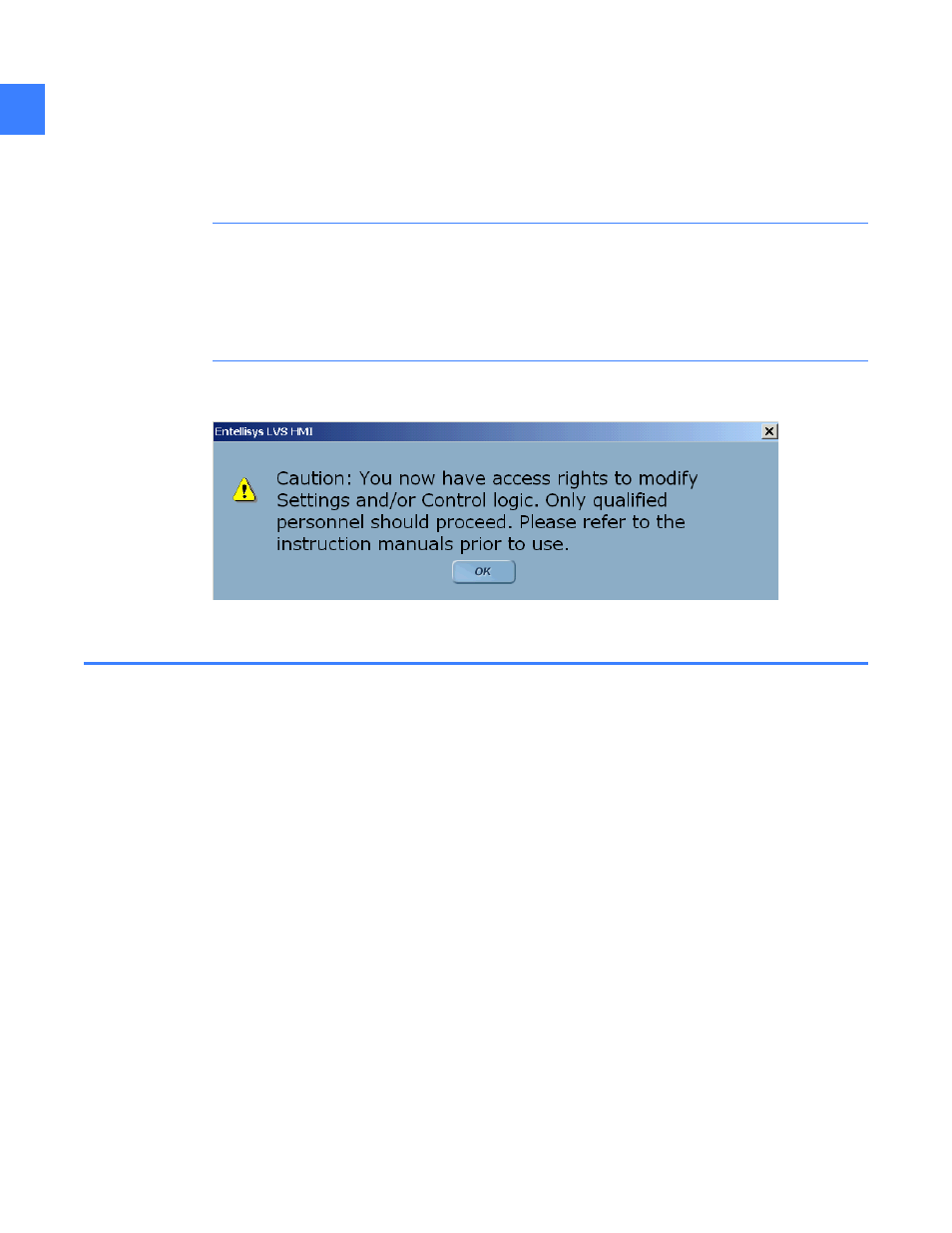
CAUTION: Users that have been assigned Group Permissions by the System Administrator for
features that allow the changing of settings and/or access to control functions must be
established as qualified personnel only. See Chapter 4 in DEH-230, Entellisys Low Voltage
Switchgear System Administrator Manual, for more information about programming user
permissions. As a reminder, users with such privileges will be presented with the following
screen upon initial login:
Figure 1-2 Initial login Caution screen
1.2 Switchgear installations
There are two primary installation methods in the switchgear:
• Standard
• Split-redundant
With standard installation, redundant components such as the CPUs, Messenger switches, and
UPSs are installed together in the equipment. This method optimizes footprint and convenience
of maintenance.
With split-redundant installation, redundant components such as the CPUs, Messenger
switches, and UPSs are split-up with at least one switchgear stack separating them. This
method optimizes system availability.
For more information, see DEH-237 Entellisys Low Voltage Switchgear Installation and
Maintenance Instruction Guide.