Reset recommendation to prevent flash corruption, Idle mode, Table 58 gi – Rainbow Electronics AT89C51SND1C User Manual
Page 47: At8xc51snd1c
47
AT8xC51SND1C
4109E–8051–06/03
Table 58. Minimum Reset Capacitor Value for a 50 k
Ω
Pull-down Resistor
(1)
Note:
1. These values assume V
DD
starts from 0V to the nominal value. If the time between 2
on/off sequences is too fast, the power-supply de-coupling capacitors may not be
fully discharged, leading to a bad reset sequence.
Warm Reset
To achieve a valid reset, the reset signal must be maintained for at least 2 machine
cycles (24 oscillator clock periods) while the oscillator is running. The number of clock
periods is mode independent (X2 or X1).
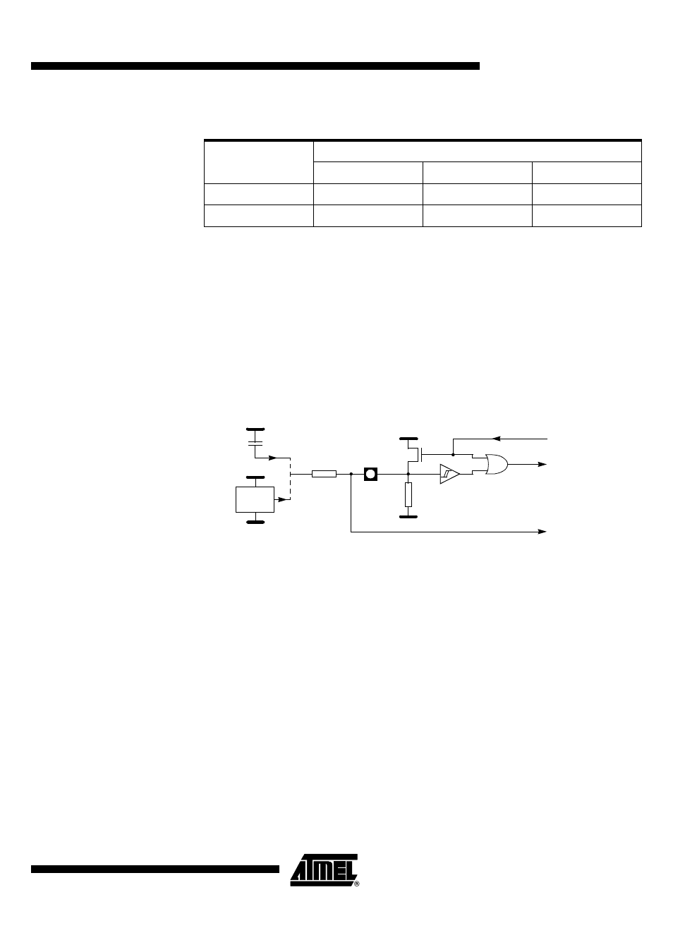
Watchdog Reset
As detailed in section “Watchdog Timer”, page 59, the WDT generates a 96-clock period
pulse on the RST pin. In order to properly propagate this pulse to the rest of the applica-
tion in case of external capacitor or power-supply supervisor circuit, a 1 k
Ω
resistor must
be added as shown in Figure 25.
Figure 25. Reset Circuitry for WDT Reset-out Usage
Reset Recommendation
to Prevent Flash
Corruption
An example of bad initialization situation may occur in an instance where the bit
ENBOOT in AUXR1 register is initialized from the hardware bit BLJB upon reset. Since
this bit allows mapping of the bootloader in the code area, a reset failure can be critical.
If one wants the ENBOOT cleared in order to unmap the boot from the code area (yet
due to a bad reset) the bit ENBOOT in SFRs may be set. If the value of Program
Counter is accidently in the range of the boot memory addresses then a Flash access
(write or erase) may corrupt the Flash on-chip memory.
It is recommended to use an external reset circuitry featuring power supply monitoring to
prevent system malfunction during periods of insufficient power supply voltage (power
supply failure, power supply switched off).
Idle Mode
Idle mode is a power reduction mode that reduces the power consumption. In this mode,
program execution halts. Idle mode freezes the clock to the CPU at known states while
the peripherals continue to be clocked (refer to section “Oscillator”, page 12). The CPU
status before entering Idle mode is preserved, i.e., the program counter and program
status word register retain their data for the duration of Idle mode. The contents of the
SFRs and RAM are also retained. The status of the Port pins during Idle mode is
detailed in Table 57.
Oscillator
Start-Up Time
VDD Rise Time
1 ms
10 ms
100 ms
5 ms
820 nF
1.2 µF
12 µF
20 ms
2.7 µF
3.9 µF
12 µF
R
RS
T
RST
VSS
To CPU Core
and Peripherals
VDD
+
P
VDD
From WDT
Reset Source
VSS
VDD
RST
1K
To Other
On-board
Circuitry