Interrupt, Figure 110, At8xc51snd1c – Rainbow Electronics AT89C51SND1C User Manual
Page 142
142
AT8xC51SND1C
4109E–8051–06/03
Interrupt
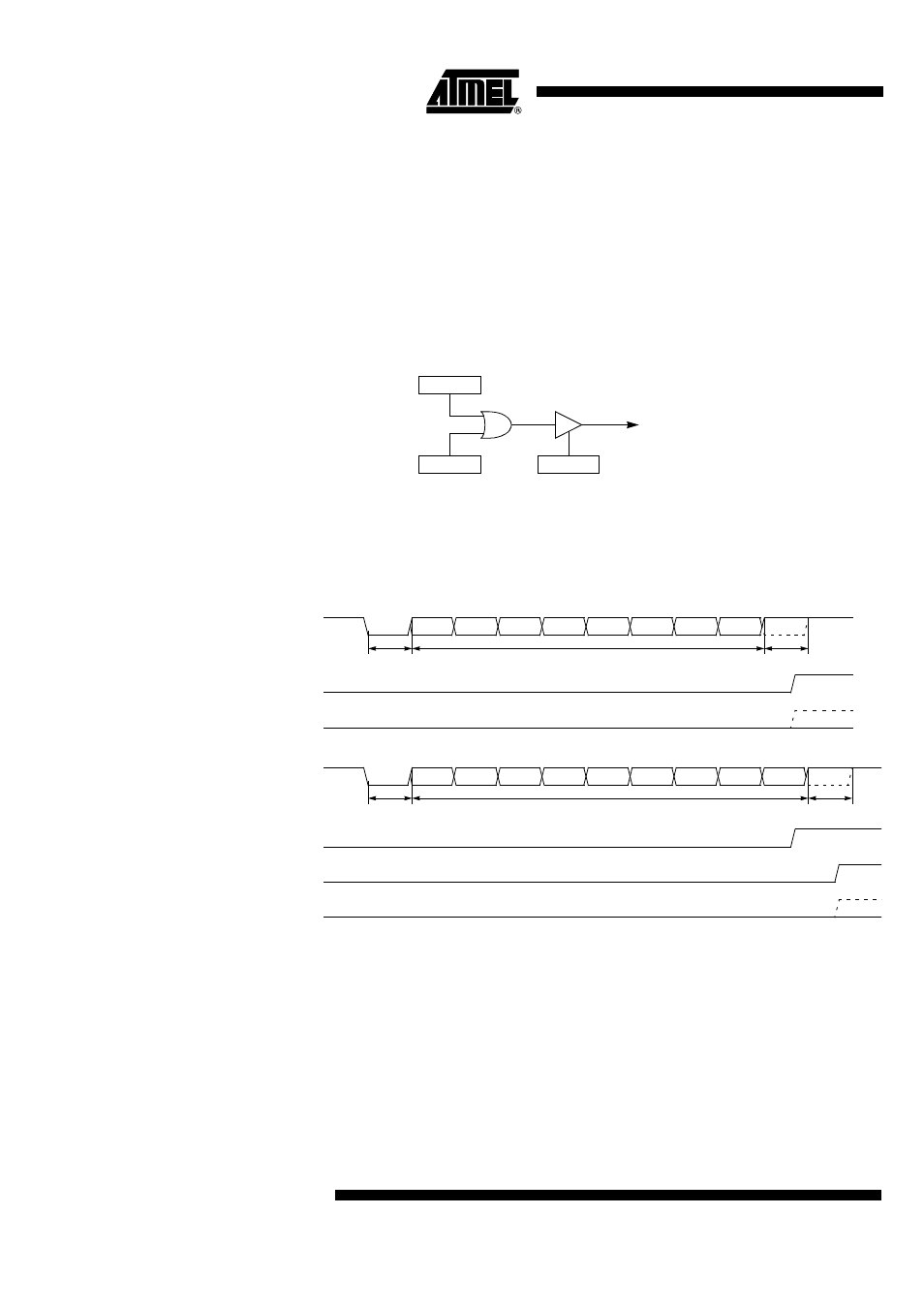
The Serial I/O Port handles 2 interrupt sources that are the “end of reception” (RI in
SCON) and “end of transmission” (TI in SCON) flags. As shown in Figure 109 these
flags are combined together to appear as a single interrupt source for the C51 core.
Flags must be cleared by software when executing the serial interrupt service routine.
The serial interrupt is enabled by setting ES bit in IEN0 register. This assumes interrupts
are globally enabled by setting EA bit in IEN0 register.
Depending on the selected mode and weather the framing error detection is enabled or
disabled, RI flag is set during the stop bit or during the ninth bit as detailed in Figure 110.
Figure 109. Serial I/O Interrupt System
Figure 110. Interrupt Waveforms
ES
IEN0.4
Serial I/O
Interrupt Request
TI
SCON.1
RI
SCON.0
RXD
D0
D1
D2
D3
D4
D5
D6
D7
Start Bit
8-bit Data
Stop Bit
RI
SMOD0 = X
FE
SMOD0 = 1
a. Mode 1
b. Mode 2 and 3
RXD
D0
D1
D2
D3
D4
D5
D6
D8
Start bit
9-bit data
Stop bit
RI
SMOD0 = 1
FE
SMOD0 = 1
D7
RI
SMOD0 = 0