Clock controller, Oscillator, X2 feature – Rainbow Electronics AT89C51SND1C User Manual
Page 12: At8xc51snd1c
12
AT8xC51SND1C
4109E–8051–06/03
Clock Controller
The AT8xC51SND1C clock controller is based on an on-chip oscillator feeding an on-
chip Phase Lock Loop (PLL). All internal clocks to the peripherals and CPU core are
generated by this controller.
Oscillator
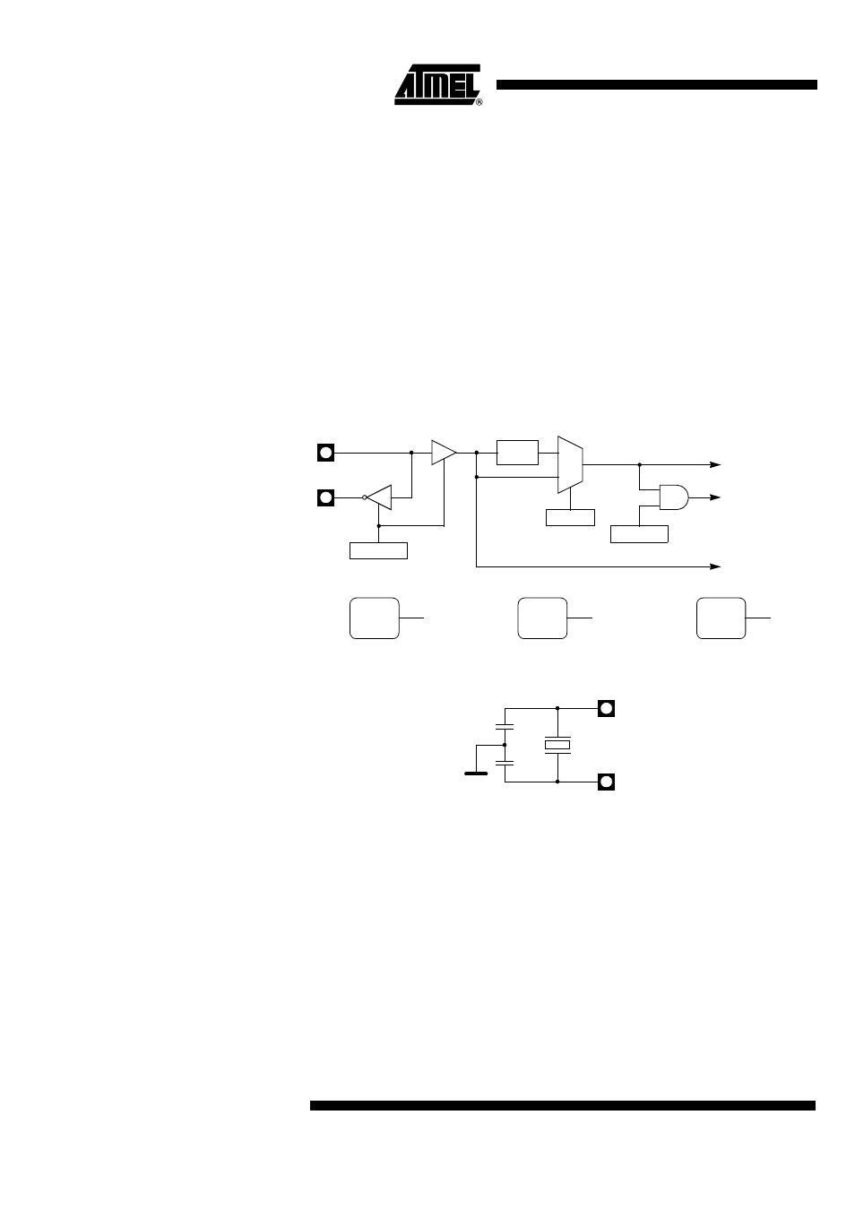
The AT8xC51SND1C X1 and X2 pins are the input and the output of a single-stage on-
chip inverter (see Figure 5) that can be configured with off-chip components such as a
Pierce oscillator (see Figure 6). Value of capacitors and crystal characteristics are
detailed in the section “DC Characteristics”.
The oscillator outputs three different clocks: a clock for the PLL, a clock for the CPU
core, and a clock for the peripherals as shown in Figure 5. These clocks are either
enabled or disabled, depending on the power reduction mode as detailed in the section
“Power Management” on page 46. The peripheral clock is used to generate the Timer 0,
Timer 1, MMC, ADC, SPI, and Port sampling clocks.
Figure 5. Oscillator Block Diagram and Symbol
Figure 6. Crystal Connection
X2 Feature
Unlike standard C51 products that require 12 oscillator clock periods per machine cycle,
the AT8xC51SND1C need only 6 oscillator clock periods per machine cycle. This fea-
ture called the “X2 feature” can be enabled using the X2 bit
(1)
in CKCON (see Table 16)
and allows the AT8xC51SND1C to operate in 6 or 12 oscillator clock periods per
machine cycle. As shown in Figure 5, both CPU and peripheral clocks are affected by
this feature. Figure 7 shows the X2 mode switching waveforms. After reset the standard
mode is activated. In standard mode the CPU and peripheral clock frequency is the
oscillator frequency divided by 2 while in X2 mode, it is the oscillator frequency.
Note:
1. The X2 bit reset value depends on the X2B bit in the Hardware Security Byte (see
Table 22 on page 22). Using the AT89C51SND1C (Flash Version) the system can
boot either in standard or X2 mode depending on the X2B value. Using
AT83C51SND1C (ROM Version) the system always boots in standard mode. X2B bit
can be changed to X2 mode later by software.
X1
X2
PD
PCON.1
IDL
PCON.0
Peripheral
CPU Core
0
1
X2
CKCON.0
÷
2
PER
CLOCK
Clock
Clock
Peripheral Clock Symbol
CPU
CLOCK
CPU Core Clock Symbol
OSC
CLOCK
Oscillator Clock Symbol
Oscillator
Clock
VSS
X1
X2
Q
C1
C2