Hardware security system, Boot memory execution, At8xc51snd1c – Rainbow Electronics AT89C51SND1C User Manual
Page 19
19
AT8xC51SND1C
4109E–8051–06/03
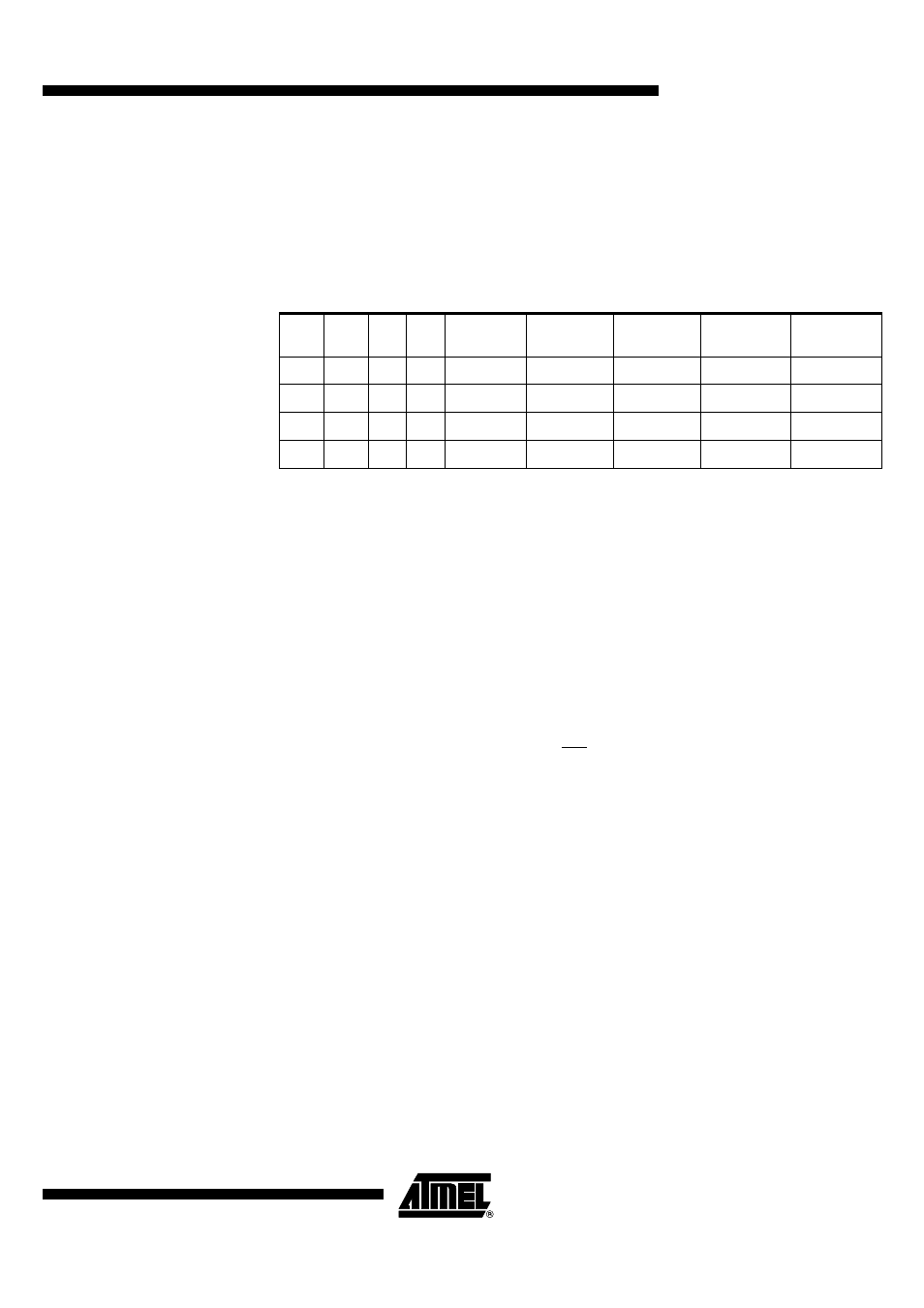
Hardware Security
System
The AT89C51SND1C implements three lock bits LB2:0 in the LSN of HSB (see
Table 22) providing three levels of security for user’s program as described in Table 22
while the AT83C51SND1C is always set in read disabled mode.
Level 0 is the level of an erased part and does not enable any security feature.
Level 1 locks the hardware programming of both user and boot memories.
Level 2 locks also hardware verifying of both user and boot memories
Level 3 locks also the external execution.
Notes:
1. U means unprogrammed, P means programmed and X means don’t care (pro-
grammed or unprogrammed).
2. LB2 is not implemented in the AT8xC51SND1C products.
3. AT89C51SND1C products are delivered with third level programmed to ensure that
the code programmed by software using ISP or user’s boot loader is secured from
any hardware piracy.
Boot Memory Execution
As internal C51 code space is limited to 64K Bytes, some mechanisms are implemented
to allow boot memory to be mapped in the code space for execution at addresses from
F000h to FFFFh. The boot memory is enabled by setting the ENBOOT bit in AUXR1
(see Figure 21). The three ways to set this bit are detailed in the following sections.
Software Boot Mapping
The software way to set ENBOOT consists in writing to AUXR1 from the user’s soft-
ware. This enables boot loader or API routines execution.
Hardware Condition Boot
Mapping
The hardware condition is based on the ISP pin. When driving this pin to low level, the
chip reset sets ENBOOT and forces the reset vector to F000h instead of 0000h in order
to execute the boot loader software.
As shown in Figure 14 the hardware condition always allows in-system recovery when
user’s memory has been corrupted.
Programmed Condition Boot
Mapping
The programmed condition is based on the Boot Loader Jump Bit (BLJB) in HSB. As
shown in Figure 14 when this bit is programmed (by hardware or software programming
mode), the chip reset set ENBOOT and forces the reset vector to F000h instead of
0000h, in order to execute the boot loader software.
Table 20. Lock Bit Features
(1)
Level
LB2
(2)
LB1
LB0
Internal
Execution
External
Execution
Hardware
Verifying
Hardware
Programming
Software
Programming
0
U
U
U
Enable
Enable
Enable
Enable
Enable
1
U
U
P
Enable
Enable
Enable
Disable
Enable
2
U
P
X
Enable
Enable
Disable
Disable
Enable
3
(3)
P
X
X
Enable
Disable
Disable
Disable
Enable