Hardware bytes, Table 22), E table 23) – Rainbow Electronics AT89C51SND1C User Manual
Page 22: Table 24), Table 22, At8xc51snd1c
22
AT8xC51SND1C
4109E–8051–06/03
Hardware Bytes
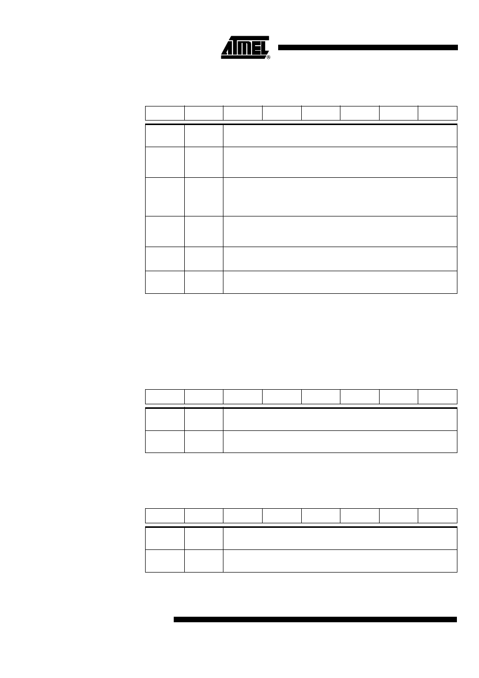
Table 22. HSB Byte – Hardware Security Byte
Reset Value = XXUU UXXX, UUUU UUUU after an hardware full chip erase.
Note:
1. X2B initializes the X2 bit in CKCON during the reset phase.
2. In order to ensure boot loader activation at first power-up, AT89C51SND1C products
are delivered with BLJB programmed.
3. Bits 0 to 3 (LSN) can only be programmed by hardware mode.
Reset Value = XXXX XXXX, UUUU UUUU after an hardware full chip erase.
Reset Value = XXXX XXXX, UUUU UUUU after an hardware full chip erase.
7
6
5
4
3
2
1
0
X2B
BLJB
-
-
-
LB2
LB1
LB0
Bit
Number
Bit
Mnemonic
Description
7
X2B
(1)
X2 Bit
Program this bit to start in X2 mode.
Unprogram (erase) this bit to start in standard mode.
6
BLJB
(2)
Boot Loader Jump Bit
Program this bit to execute the boot loader at address F000h on next reset.
Unprogram (erase) this bit to execute user’s application at address 0000h on
next reset.
5 - 4
-
Reserved
The value read from these bits is always unprogrammed. Do not program these
bits.
3
-
Reserved
The value read from this bit is always unprogrammed. Do not program this bit.
2 - 0
LB2:0
Hardware Lock Bits
Refer to for bits description.
Table 23. SBV Byte – Software Boot Vector
7
6
5
4
3
2
1
0
ADD15
ADD14
ADD13
ADD12
ADD11
ADD10
ADD9
ADD8
Bit
Number
Bit
Mnemonic
Description
7 - 0
ADD15:8
MSB of the user’s boot loader 16-bit address location
Refer to the boot loader datasheet for usage information (boot loader dependent)
Table 24. SSB Byte – Software Security Byte
7
6
5
4
3
2
1
0
SSB7
SSB6
SSB5
SSB4
SSB3
SSB2
SSB1
SSB0
Bit
Number
Bit
Mnemonic
Description
7 - 0
SSB7:0
Software Security Byte Data
Refer to the boot loader datasheet for usage information (boot loader dependent)