Registers, Figure 21), At8xc51snd1c – Rainbow Electronics AT89C51SND1C User Manual
Page 21
21
AT8xC51SND1C
4109E–8051–06/03
Registers
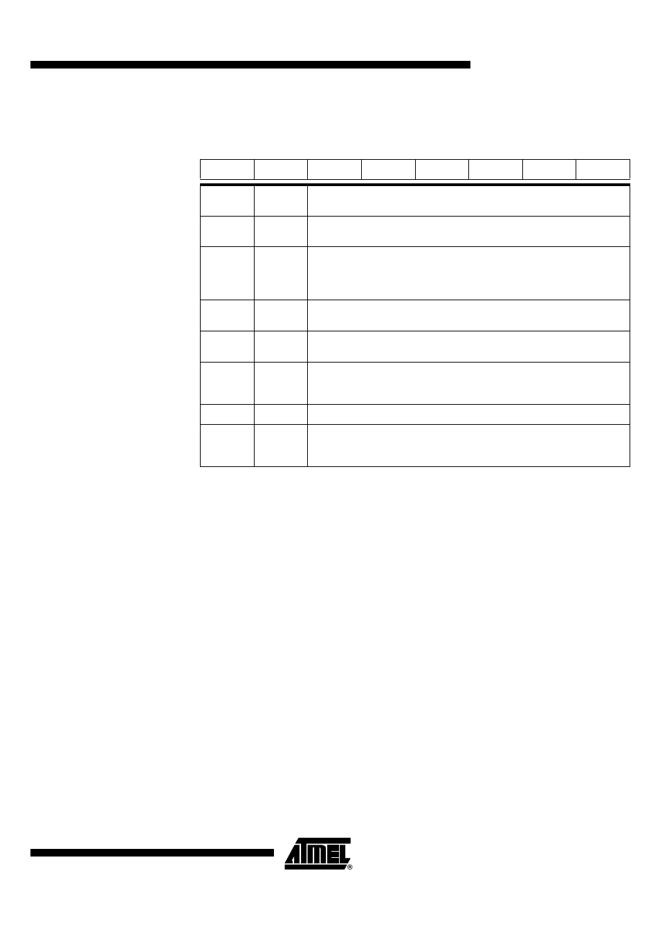
Table 21. AUXR1 Register
AUXR1 (S:A2h) – Auxiliary Register 1
Reset Value = XXXX 00X0b
Note:
1. ENBOOT bit is only available in AT89C51SND1C product.
7
6
5
4
3
2
1
0
-
-
ENBOOT
-
GF3
0
-
DPS
Bit
Number
Bit
Mnemonic
Description
7 - 6
-
Reserved
The value read from these bits are indeterminate. Do not set these bits.
5
ENBOOT
1
Enable Boot Flash
Set this bit to map the boot Flash in the code space between at addresses F000h
to FFFFh.
Clear this bit to disable boot Flash.
4
-
Reserved
The value read from this bit is indeterminate. Do not set this bit.
3
GF3
General Flag
This bit is a general-purpose user flag.
2
0
Always Zero
This bit is stuck to logic 0 to allow INC AUXR1 instruction without affecting GF3
flag.
1
-
Reserved for Data Pointer Extension.
0
DPS
Data Pointer Select Bit
Set to select second data pointer: DPTR1.
Clear to select first data pointer: DPTR0.
- MAX5151 (16 pages)
- MAXQ3108 (64 pages)
- MAX5661 (39 pages)
- MAX6691 (7 pages)
- MAX5362 (12 pages)
- ADC10158 (26 pages)
- MAX8922L (14 pages)
- MAX8596Z (8 pages)
- MAX7491 (18 pages)
- MAX15040 (15 pages)
- MAX5177 (16 pages)
- ADC08138 (22 pages)
- MAX5961 (42 pages)
- T89C51RD2 (86 pages)
- MAX16055 (9 pages)
- MAX6659 (17 pages)
- ADC0820 (20 pages)
- MAX6678 (19 pages)
- MAX8884Z (15 pages)
- MAX16915 (9 pages)
- MAX8620 (18 pages)
- MAX5144 (12 pages)
- MAX6670 (8 pages)
- MAX8760 (39 pages)
- W78C32C (14 pages)
- MX7533 (8 pages)
- MAX8727 (13 pages)
- MAX9053 (15 pages)
- W78C54 (16 pages)
- MAX8614B (15 pages)
- W90N740 (219 pages)
- MAX6626 (13 pages)
- ADC10738 (30 pages)
- MAX17000 (31 pages)
- MAX5051 (21 pages)
- MAXQ1004 (18 pages)
- MAX6871 (51 pages)
- MX7847 (12 pages)
- MAX6608 (6 pages)
- MAX17083 (15 pages)
- MAX6641 (17 pages)
- MAX5251 (16 pages)
- MAX6338 (8 pages)
- MAX6690 (16 pages)
- MAX8668 (18 pages)