Registers, Table 16), At8xc51snd1c – Rainbow Electronics AT89C51SND1C User Manual
Page 15
15
AT8xC51SND1C
4109E–8051–06/03
Registers
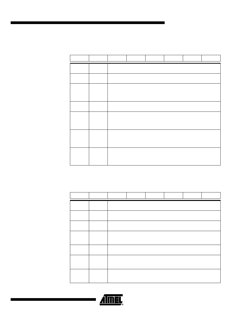
Table 16. CKCON Register
CKCON (S:8Fh) – Clock Control Register
Reset Value = 0000 000Xb (AT89C51SND1C) or 0000 0000b (AT83C51SND1C)
Table 17. PLLCON Register
PLLCON (S:E9h) – PLL Control Register
Reset Value = 0000 1000b
7
6
5
4
3
2
1
0
-
WDX2
-
-
-
T1X2
T0X2
X2
Bit
Number
Bit
Mnemonic
Description
7
-
Reserved
The value read from this bit is indeterminate. Do not set this bit.
6
WDX2
Watchdog Clock Control Bit
Set to select the oscillator clock divided by 2 as watchdog clock input (X2
independent).
Clear to select the peripheral clock as watchdog clock input (X2 dependent).
5 - 3
-
Reserved
The values read from these bits are indeterminate. Do not set these bits.
2
T1X2
Timer 1 Clock Control Bit
Set to select the oscillator clock divided by 2 as timer 1 clock input (X2
independent).
Clear to select the peripheral clock as timer 1 clock input (X2 dependent).
1
T0X2
Timer 0 Clock Control Bit
Set to select the oscillator clock divided by 2 as timer 0 clock input (X2
independent).
Clear to select the peripheral clock as timer 0 clock input (X2 dependent).
0
X2
System Clock Control Bit
Clear to select 12 clock periods per machine cycle (STD mode, F
CPU
= F
PER
=
F
OSC
/
2).
Set to select 6 clock periods per machine cycle (X2 mode, F
CPU
= F
PER
= F
OSC
).
7
6
5
4
3
2
1
0
R1
R0
-
-
PLLRES
-
PLLEN
PLOCK
Bit
Number
Bit
Mnemonic
Description
7 - 6
R1:0
PLL Least Significant Bits R Divider
2 LSB of the 10-bit R divider.
5 - 4
-
Reserved
The values read from these bits are always 0. Do not set these bits.
3
PLLRES
PLL Reset Bit
Set this bit to reset the PLL.
Clear this bit to free the PLL and allow enabling.
2
-
Reserved
The value read from this bit is always 0. Do not set this bit.
1
PLLEN
PLL Enable Bit
Set to enable the PLL.
Clear to disable the PLL.
0
PLOCK
PLL Lock Indicator
Set by hardware when PLL is locked.
Clear by hardware when PLL is unlocked.