E table 144), E table 143) and, Table 145) – Rainbow Electronics AT89C51SND1C User Manual
Page 173: At8xc51snd1c
173
AT8xC51SND1C
4109E–8051–06/03
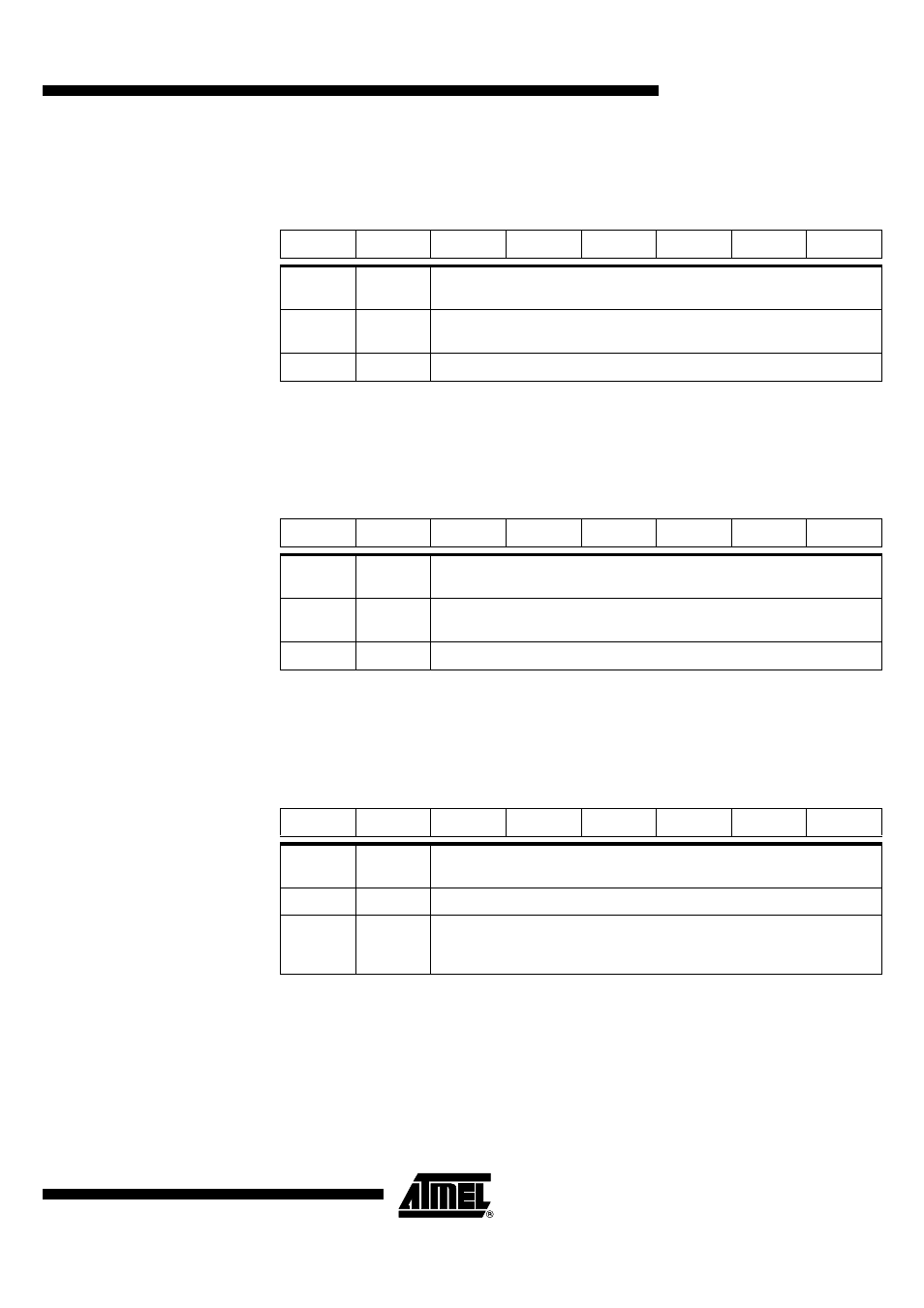
Table 143. SSSTA Register
SSSTA (S:94h) – Synchronous Serial Status Register
Reset Value = F8h
Table 144. SSDAT Register
SSDAT (S:95h) – Synchronous Serial Data Register
Reset Value = 1111 1111b
Table 145. SSADR Register
SSADR (S:96h) – Synchronous Serial Address Register
Reset Value = 1111 1110b
7
6
5
4
3
2
1
0
SSC4
SSC3
SSC2
SSC1
SSC0
0
0
0
Bit
Number
Bit
Mnemonic
Description
7:3
SSC4:0
Synchronous Serial Status Code Bits 0 to 4
Refer to Table 136 to Table 128 for status description.
2:0
0
Always 0.
7
6
5
4
3
2
1
0
SSD7
SSD6
SSD5
SSD4
SSD3
SSD2
SSD1
SSD0
Bit
Number
Bit
Mnemonic
Description
7:1
SSD7:1
Synchronous Serial Address bits 7 to 1 or Synchronous Serial Data Bits 7
to 1
0
SSD0
Synchronous Serial Address bit 0 (R/W) or Synchronous Serial Data Bit 0
7
6
5
4
3
2
1
0
SSA7
SSA6
SSA5
SSA4
SSA3
SSA2
SSA1
SSGC
Bit
Number
Bit
Mnemonic
Description
7:1
SSA7:1
Synchronous Serial Slave Address Bits 7 to 1
0
SSGC
Synchronous Serial General Call Bit
Set to enable the general call address recognition.
Clear to disable the general call address recognition.