Table 146), At8xc51snd1c – Rainbow Electronics AT89C51SND1C User Manual
Page 175
175
AT8xC51SND1C
4109E–8051–06/03
Clock Generator
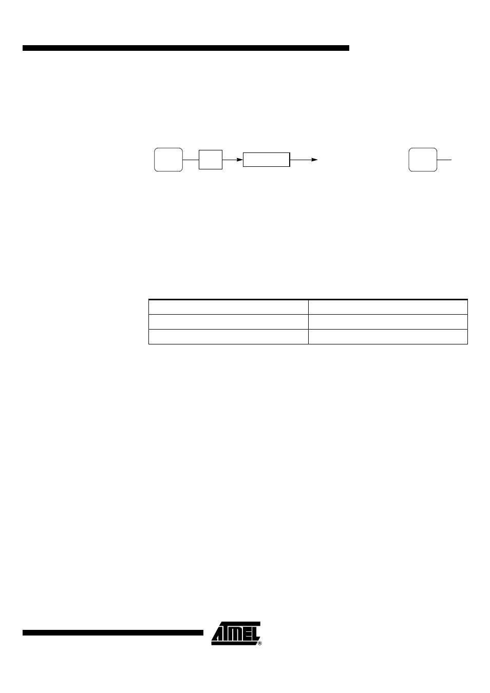
The ADC clock is generated by division of the peripheral clock (see details in
section “X2 Feature”, page 12). The division factor is then given by ADCP4:0 bits in
ADCLK register. Figure 131 shows the ADC clock generator and its calculation
formula
(1)
.
Figure 131. ADC Clock Generator and Symbol Caution:
Note:
1. In all cases, the ADC clock frequency may be higher than the maximum F
ADCLK
parameter reported in the section “Analog to Digital Converter”, page 197.
2. The ADCD value of 0 is equivalent to an ADCD value of 32.
Channel Selection
The channel on which conversion is performed is selected by the ADCS bit in ADCON
register according to Table 146.
Table 146. ADC Channel Selection
Conversion Precision
The 10-bit precision conversion is achieved by stopping the CPU core activity during
conversion for limiting the digital noise induced by the core. This mode called the
Pseudo-Idle mode
(1),(2)
is enabled by setting the ADIDL bit in ADCON register
(3)
. Thus,
when conversion is launched (see Section "Conversion Launching", page 176), the
CPU core is stopped until the end of the conversion (see Section "End Of Conversion",
page 176). This bit is cleared by hardware at the end of the conversion.
Notes:
1. Only the CPU activity is frozen, peripherals are not affected by the Pseudo-Idle
mode.
2. If some interrupts occur during the Pseudo-Idle mode, they will be delayed and pro-
cessed, according to their priority after the end of the conversion.
3. Concurrently with ADSST bit.
Configuration
The ADC configuration consists in programming the ADC clock as detailed in the Sec-
tion "Clock Generator", page 175. The ADC is enabled using the ADEN bit in ADCON
register. As shown in Figure 93, user must wait the setup time (T
SETUP
) before launching
any conversion.
ADCD4:0
ADCLK
ADC Clock
ADCclk
PERclk
2 ADCD
⋅
-------------------------
=
ADC Clock Symbol
ADC
CLOCK
PER
CLOCK
÷
2
ADCS
Channel
0
AIN1
1
AIN0