7 wiring the power supply, Installation and wiring, User’s manual – Toshiba T2N User Manual
Page 80
4.Installation and Wiring
User’s manual
65
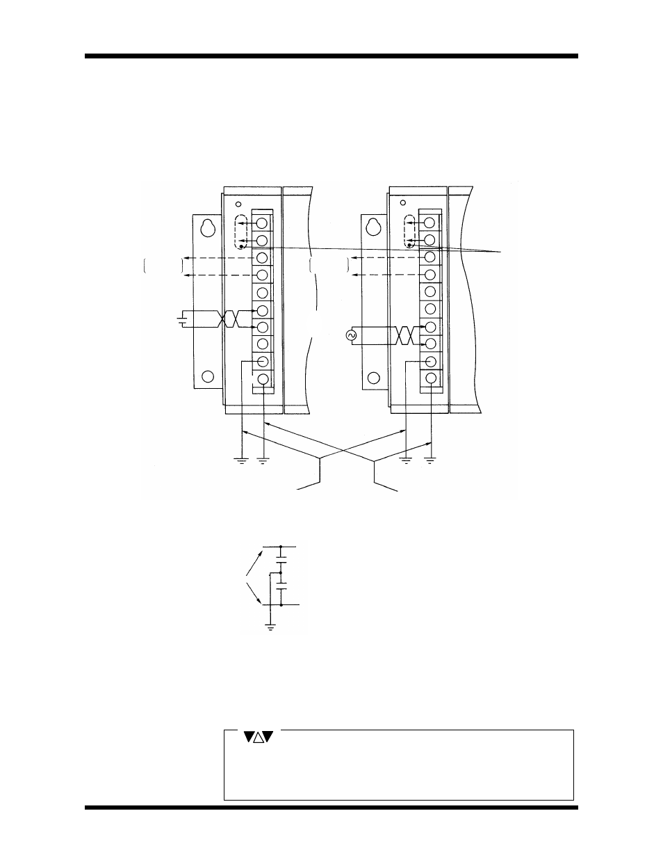
Wire the external power supply to the T2N power supply module in the following
manner.
When using expansion units, arrange for power to be supplied simultaneouly to
the basic unit and the expansion units (or to the expansion units before the
basic unit).
PS31 (24Vdc input)
PS261 (100 - 240Vac input)
RUN
contact
output
RUN
contact
output
24Vdc output *3
(Total power of the
internal 5V and 24V
output must be
within 15W.
Do not connect it to
other power supply
systems.)
Input
power supply
24Vdc
Line filters ground *1 (Connected to the supply
line via capacitors)
Frame ground *2 (Connected to the unit
case)
NC
NC
NC
LG
FG
FG
FG
NC
+
-
Input
power supply
*1 : Line Filter Ground(LG)
LG
5000PF or less
5000PF or less
Input
power supply
*2 : Frame Gounds(FG)
See 4.5 Grounding for details.
*3 : 24Vdc output
The 24Vdc power cables must be suppressed with ferrite cores, immediately
adjacent to the power supply module(s).
Use crimp-style terminals with sheaths as far as possible for wiring to the
power supply module. When it is not possible to use crimp-style terminals
with sheaths, cover with insulating tape so that the conductive parts are not
exposed.
Normally, the LG and FG terminals are
shorted.
However, depending on grounding
environment (such as when there is a
problem with leakage current or when the
power supply ground is separate), open the
LG terminal or provide a dedicated ground.
NOTE
4.7
Wiring
the Power Supply